February 2012 20 – 325
20.5 Troubleshooting
Examining the
encoders
8 See “Encoder interface” on page 19 – 277.
Examining the
reference mark
8 See “Further examination of position and speed encoders” on page 19 – 314.
Examining the
trigger signal of
the trip dog
8 Ask the machine manufacturer for the PLC input for the trigger signal.
8 Move the axis to the presumed position of the trip dog.
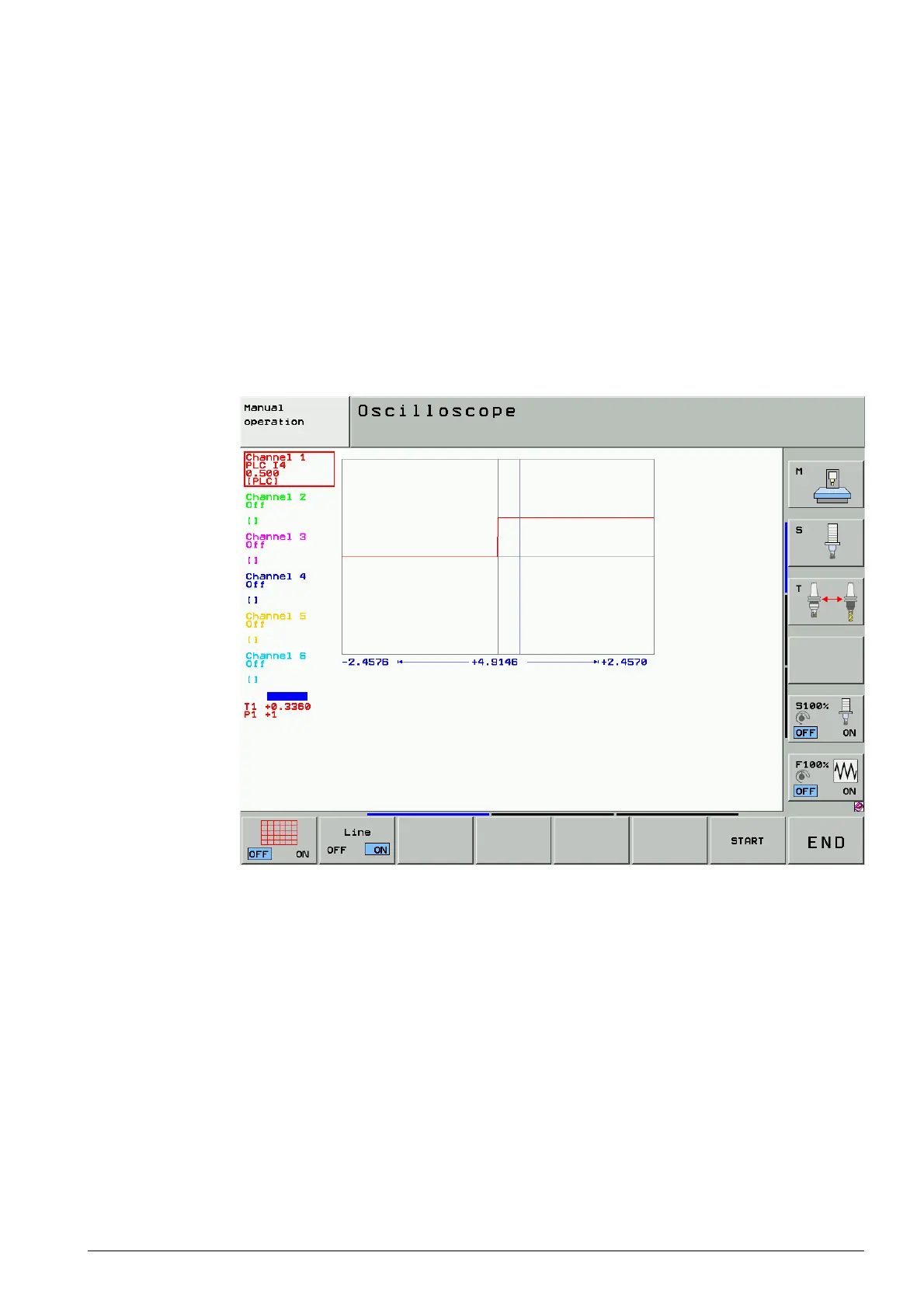
8 Observe the trigger signal, e.g. in the integrated oscilloscope or in the PLC logic diagram.
Figure: Trigger signal of the trip dog in the integrated oscilloscope

 Loading...


