February 2012 28 – 493
28.9 PSL low-voltage power supply unit
28.9.1 Designations and positions of connectors
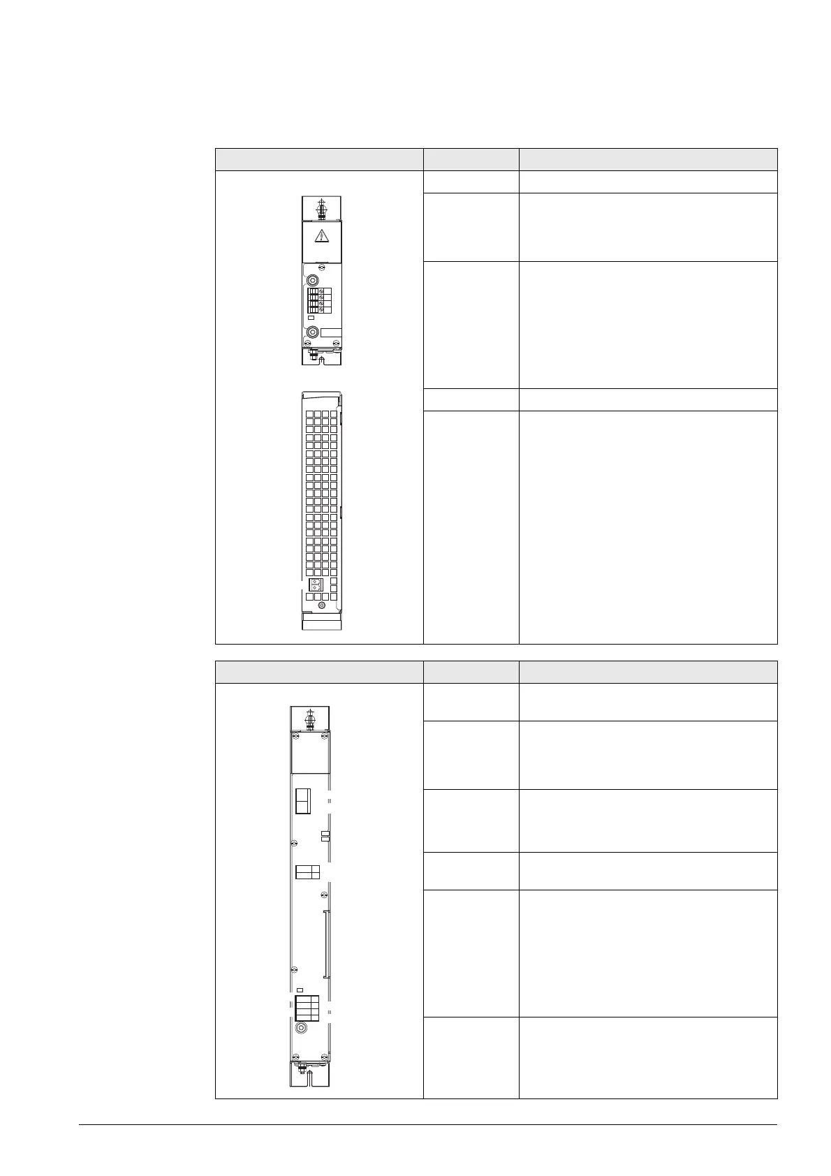
PSL 130 pin layout Connector Function
Conductor bar Connection of DC-link voltage Uz
B – Signal
ground
(= functional
ground)
Signal ground (0 V signal of the +24 V NC
signal connected internally to protective
ground)
X90 Output for supply voltages:
Terminal 1: +24 V NC
Terminal 2: 0 V NC
(ground +24 V NC)
Terminal 3: + 24 V PLC
Terminal 4 0 V PLC
(ground +24 V– PLC)
X33 Input voltages L1, L2
Protective ground
PSL 135 pin layout Connector Function
X31 Input voltages L1, L2 and connection of the
DC-link voltage Uz
B – Signal
ground
(= functional
ground)
Signal ground (0 V signal of the +24 V NC
signal connected internally to protective
ground)
X74 Output for supply voltages:
Terminal 1: +5 V
Terminal 2: 0 V
X69 Power supply and control signals for CC 61xx
(for X69 on CC)
X90 Output for supply voltages:
Terminal 1: +24 V NC
Terminal 2: 0 V NC
(ground +24 V NC)
Terminal 3: + 24 V PLC
Terminal 4 0 V PLC
(ground +24 V– PLC)
Protective ground
X31
X74
X69
X90
L1/L2
+U
DC
/ U
DC
+5V
0V
24V
0V
0V
24V

 Loading...


