28 – 494 HEIDENHAIN Service Manual iTNC 530 HSCI
28.9.2 Pin layouts
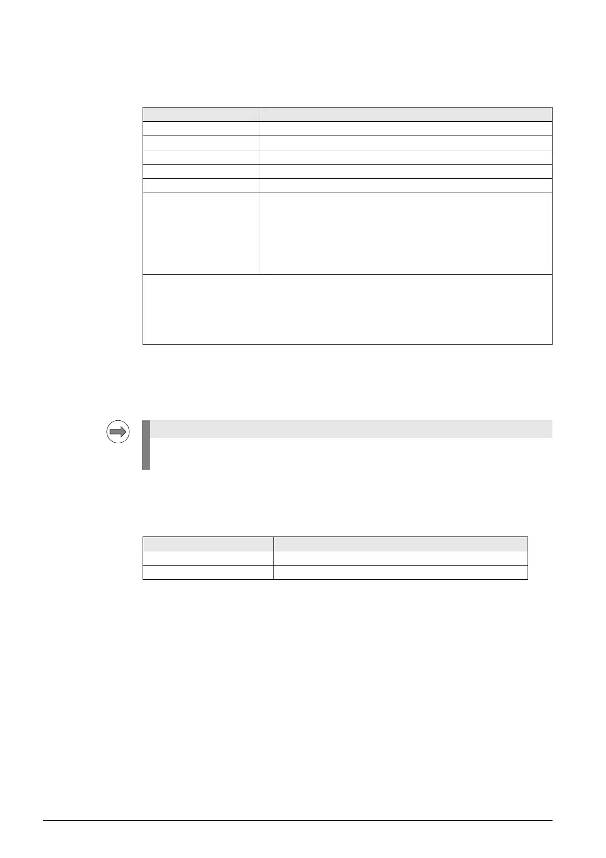
X31:
Input voltage of
the PSL 135
Supply voltage: 400 V ± 10 % or 400 V– to 750 V–
Through the connection to the 400 V AC line voltage (L1, L2) via X31, the output voltages of the
PSL 135 are available as soon as the machine’s main switch has been turned on.
This is necessary to boot the control.
Conductor bars:
Supply of the
PSL 130 with U
Z
Connecting terminal Assignment
L1 Phase 1 / 400 V~ ±10 % / 50 Hz to 60 Hz
L2 Phase 2 / 400 V~ ±10 % / 50 Hz to 60 Hz
+U
DC
400 V– to 750 V–
–U
DC
0 V–
Equipment ground (YL/GN), ≥ 10 mm
2
Connecting lead:
Wire cross section: at least 1.5 mm
2
(AWG 16)
Conductor protection:
Fuses or a motor protection switch of 6.3 A or greater depending on the
wire cross section used.
Line fuse:
Internal protection of the PSL (4 A).
Tightening torque:
for the connecting terminals 0.5 - 0.6 Nm
Grounding terminal:
≥ 10 mm
2
(AWG 6)
Strain relief:
Ensure that the connecting cables are not subject to excessive strain.
HEIDENHAIN recommends connecting the PSL 135 power supply unit to the U
Z
DC-link voltage
and the 400 V supply voltage (X31).
Connecting terminals Assignment
–U
Z
DC-link voltage –
+U
Z
DC-link voltage +

 Loading...


