28 – 474 HEIDENHAIN Service Manual iTNC 530 HSCI
28.4.2 Pin layouts
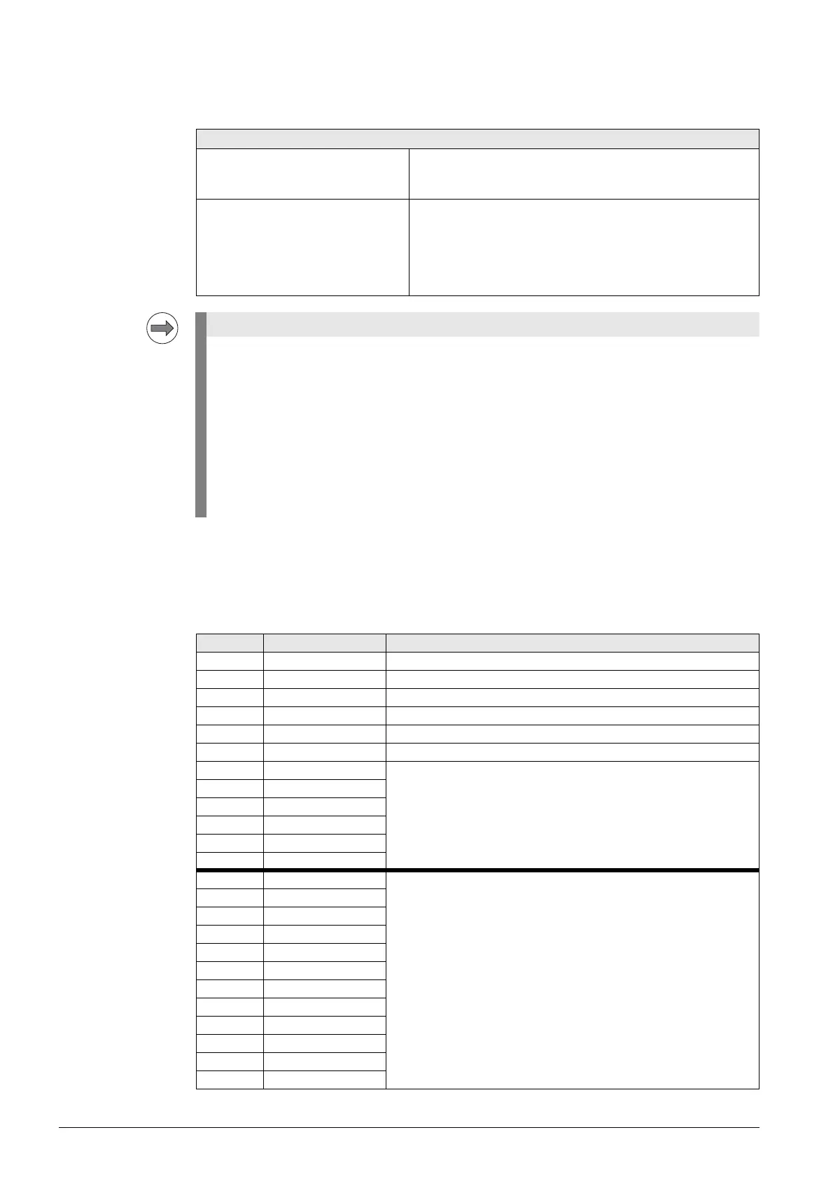
Type of terminals
on the UEC 11x
X4:
Single-channel
PLC inputs
Connections on the front of the UEC 11x:
18 single-channel PLC inputs are freely available:
I0 to I17
Socket connectors X4, X5, X6 on UEC 11x
Connection Socket connector with tension clamp connection, type:
Weidmüller B2L 3.5/24 SN SW
2-row, 24-pin
Connectable conductors Usable conductor cross sections without wire-end sleeve:
0.08 mm
2
to 1.0 mm
2
Usable conductor cross sections with wire-end sleeve:
0.14 mm
2
0.34 mm
2
0.5 mm
2
(only with Weidmüller PZ 6/5 crimping pliers)
HEIDENHAIN recommends:
Preferably use a conductor cross section of 0.34 mm
2
if you use stranded wires with wire-end
sleeves. This cross section can be clamped appropriately and ensures a reliable terminal
connection.
If you use stranded wires with wire-end sleeves and a conductor cross section of 0.5 mm
2
,
the Weidmüller PZ 6/5 crimping pliers (setting 0.25–0.5 mm
2
) must be used for crimping.
In this case, orient the crimped wire-end sleeve before inserting it into the socket connector.
If crimping pliers from other manufacturers are used for crimping conductors with a cross section
of 0.5 mm
2
, the crimped wire-end sleeves cannot be inserted into the socket connector and
clamped appropriately, and therefore do not result in a reliable terminal connection.
Terminal Signal designation Assignm. / Function
1a +24 V PLC.01 24 V supply of the outputs MC.RDY, O16 to O22
2a +24 V PLC.02 24 V supply of the outputs O8 to O15
3a +24 V PLC.03 24 V supply of the outputs O0 to O7
4a 0 V PLC 0 V for all I/Os
5a –REF.SP Reserved, do not assign
6a 0 V PLC 0 V for all I/Os
7a I12 24 V inputs
8a I13
9a I14
10a I15
11a I16
12a I17
1b I0 24 V inputs
2b I1
3b I2
4b I3
5b I4
6b I5
7b I6
8b I7
9b I8
10b I9
11b I10
12b I11

 Loading...


