February 2012 19 – 279
EnDat encoders EnDat encoders may be connected to all position encoder inputs of a CC 61xx or a UEC 11x.
Memory areas in
the EnDat encoder
EnDat encoders offer the possibility of storing machine or system-dependent data in the memory
area reserved for the machine tool builder.
19.1.2 Machine parameters
Monitoring of the
position encoders
The monitoring functions for the position encoders of the axes are activated in MP20.x.
The monitoring functions for the position encoders of the spindles are activated in MP21.x.
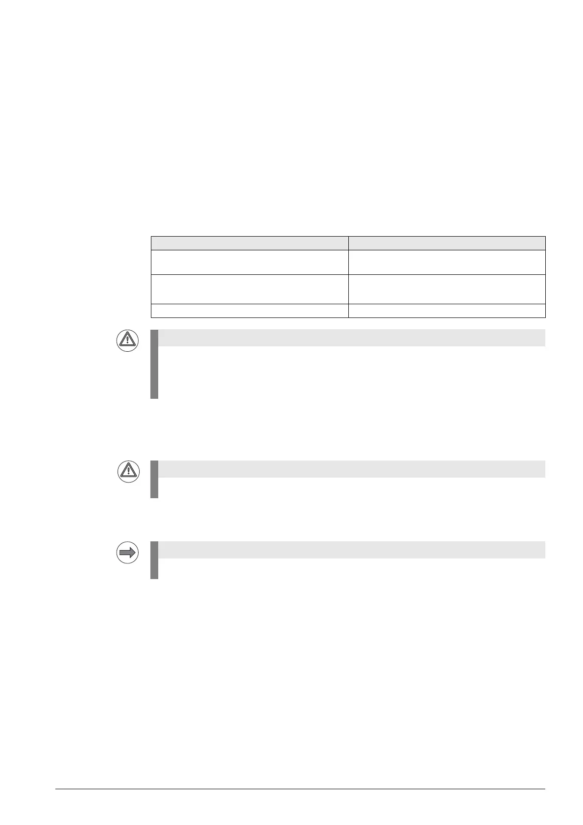
The following criteria are checked:
Connection of the
position encoders
MP100 is read from the right to the left and contains the information which axis is the first, the second,
the third, etc.
In MP108 you can see the assignment of the axes to the controller basic boards.
In MP109 you can see the assignment of the spindles to the controller basic boards.
In MP110 you can see the assignment of the axes to the position encoder inputs (connector X201 and
following).
In MP111 you can see the assignment of the spindles to the position encoder inputs (connector X201
and following).
Criterion Error message
Absolute position with distance-coded reference
marks
Position encoder <AXIS> defective
Amplitude of encoder signals Position encoder <AXIS >: amplitude too high
Position encoder <AXIS>: amplitude too low
Edge separation of encoder signals Position encoder <AXIS>: frequency too high
The monitoring functions for the position encoders (MP20.x, MP21.x) must always be active!
Safe machine operation is not ensured without these monitoring functions.
Exception:
MP20.0 and MP21.0 are only active for position encoders with distance-coded reference marks.
MP100 must not be changed!
The input value (0 ... 3) represents the HSCI address of the respective controller basic board.

 Loading...


