February 2012 18 – 271
18.13 Power supply for the control-is-ready signal
UEC 11x The Control-Is-Ready output of the UEC 11x is powered with 24 V PLC voltage via connector X34 /
terminal 1a (0 V PLC on terminal 6a).
PLB 62xx The Control-Is-Ready output of the PLB 62xx is powered with 24 V PLC voltage via connector X9 /
terminal 1a (0 V PLC on terminal 2b).
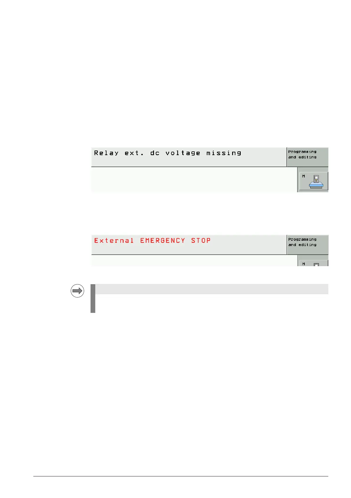
Error messages If the 24 V supply for the Control-Is-Ready output is missing, the machine cannot be switched on
completely. The EMERGENCY STOP chain is interrupted.
The control remains at the message Relay ext. dc voltage missing:
If the 24 V supply for the Control-Is-Ready output drops during machine operation, the EMERGENCY
STOP chain is interrupted. The error message
EXTERNAL EMERGENCY STOP is displayed:
Troubleshooting 8 UEC 11x: Measure the 24 V voltage at connector X4 between terminal 1a and 6a
(tolerance range 20.4 - 28.8 V).
8 PLB 62xx: Measure the 24 V voltage at connector X9 between terminal 1a and 2b
(tolerance range 20.4 - 28.8 V).
8 Check the wiring. (Use the circuit diagram of the machine tool for this purpose.)
The Control-Is-Ready output must be integrated correctly in the EMERGENCY STOP chain.
--> See ”Annex: Basic circuit diagrams of the iTNC 530 HSCI control” on page 2 – 651.

 Loading...


