18 – 272 HEIDENHAIN Service Manual iTNC 530 HSCI
18.14 Power supply of the PLB 62xx system module
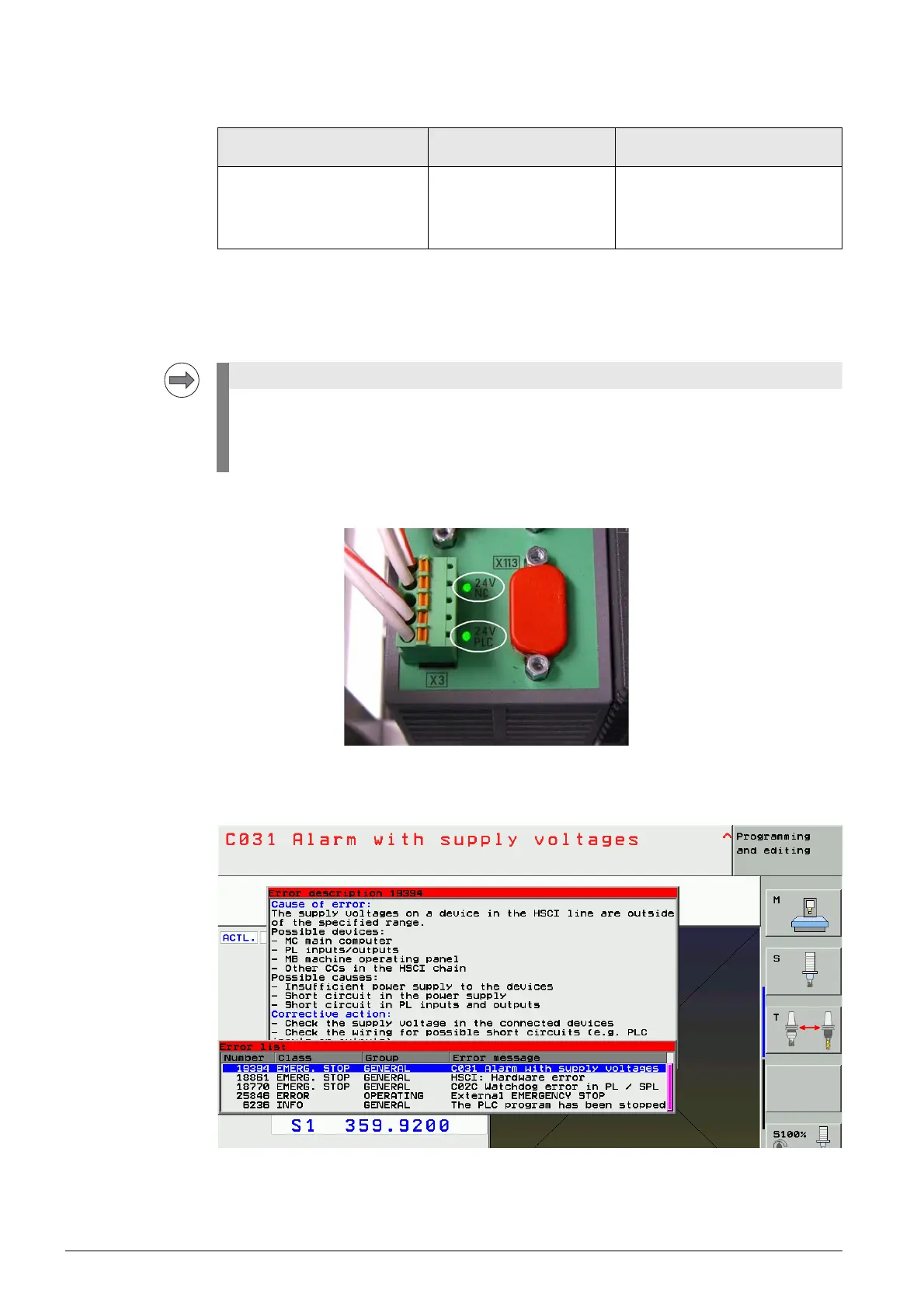
Further information and connector layout of X3 --> See ”Connector designations and pin layouts” on
page 28 – 453.
Supply voltages: +24 V NC and +24 V PLC
Current consumption NC: 0.5 A
LED display The green LEDs indicate that the connector X3 is correctly supplied with 24 V NC and 24 V PLC.
Error messages If the 24 V PLC voltage at X3 / terminal 4 drops during machine operation, the following error
messages may be issued:
8 Try to delete all error messages with the CE key. --> The permanent errors will remain in the ERR list.
Device powering the PLB 62xx
(alternatives)
Connector for PLB 62xx
power supply
Devices and outputs powered by
PLB 62xx
UEC 11x
PSL 130
PSL 135
24 V power supply unit
X3 Touch probes
Safety-related PLC outputs
The PLB 62xx features "polyfuses".
Polyfuses are electronic fuses that become highly resistive if an overload occurs and thus
separate defective peripherals (e.g., touch probes) from the low voltages of the PLB 62xx.
Polyfuses have a self-resetting function ("self-healing effect").

 Loading...


