February 2012 18 – 267
18.9 Power supply of the UEC 11x feedback control unit
Further information and connector layout of X31 --> See ”Connector designations and pin layouts”
on page 28 – 453.
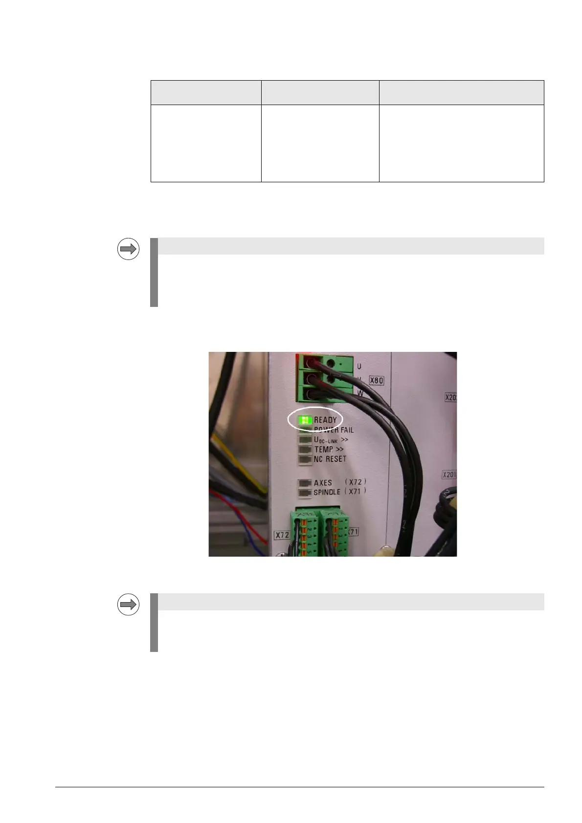
LED display The readiness indicator of the UEC 11x is the green READY LED.
During machine operation no red LEDs should shine!
Error messages
Errors If two or all three phases are missing at X31, the UEC 11x cannot operate.
If only one phase is missing, the UEC 11x may operate until the load becomes too high (e.g. when
milling a workpiece).
Troubleshooting
8 Observe the LEDs.
8 Measure the voltage at X31.
8 Disconnect all devices from the UEC (label them beforehand).
Power supply of UEC 11x Connector for UEC 11x
power supply
Devices and outputs powered
by UEC 11x
3 x 400 Vac (+/- 10%)
or
3 x 480 Vac (+/- 10%)
X31 MC 62xx
Speed encoders
Position encoders
Touch probes
PLC outputs
Motors for axes and spindle
The UEC 11x features "polyfuses".
Polyfuses are electronic fuses that become highly resistive if an overload occurs and thus
separate defective peripherals (e.g., scales, motor encoders) from the low voltages of the
UEC 11x . Polyfuses are equipped with a self-resetting function ("self-healing effect").
The most important voltage for powering the electronics is the 5 V supply voltage. The control
monitors these 5 V and generates an error message (e.g. 5-V power supply too low), if the
deviation becomes too large.

 Loading...


