18 – 268 HEIDENHAIN Service Manual iTNC 530 HSCI
18.10 Power supply of the MB 620 machine operating panel
Further information and connector layout of X101 --> See ”Connector designations and pin layouts”
on page 28 – 453.
Supply voltage: +24 Vdc
Current consumption: 1.0 A
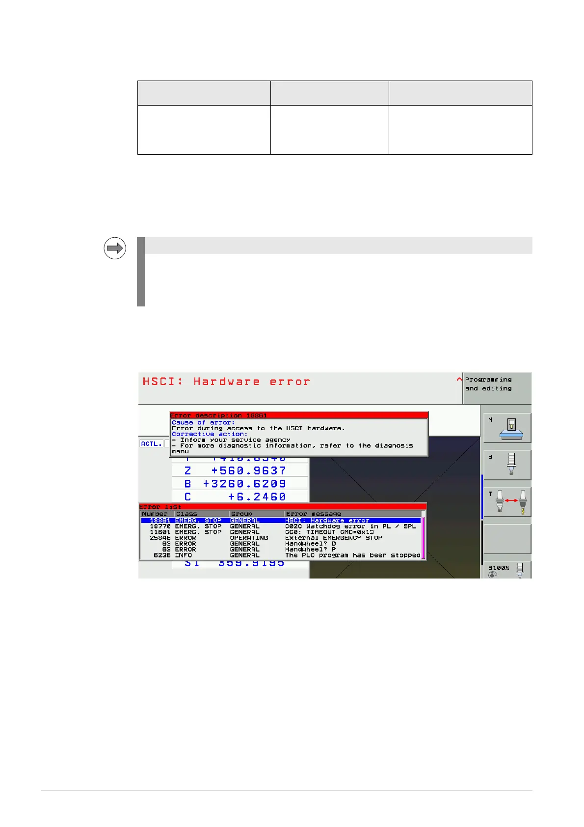
Error messages If the 24 Vdc voltage at X101 drops during machine operation, the following error messages may be
issued:
8 Try to delete all error messages with the CE key. --> The permanent errors will remain in the ERR list.
If the 24 V supply voltage at X101 is already missing during startup, the MB 620 is not found in the
HSCI bus system.
The message Hardware/firmware change detected is displayed.
--> See ”Message Hardware/firmware change detected” on page 18 – 245.
Troubleshooting
8 Measure the 24 V voltage at X101.
8 Check the function of the potentiometers on the keyboard unit.
8 If available: Check the function of the connected handhweel. You may have to disconnect it
from the MB.
8 In the window Hardware/firmware change detected, click reject and then call the HSCI bus
diagnosis. --> See ”Bus diagnosis” on page 12 – 147.
Device powering the MB 620
(alternatives)
Connector for MB 620
power supply
Devices and outputs powered by
MB 620
UEC 11x
PSL 130
PSL 135
X101 Handwheels
PLC outputs
Potentiometers on the
keyboard unit
The MB 620 features "polyfuses".
Polyfuses are electronic fuses that become highly resistive if an overload occurs and thus
separate defective peripherals (e.g., handwheel) from the low voltages of the MB 620.
Polyfuses have a self-resetting function ("self-healing effect").

 Loading...


