February 2012 1 – 641
1 Annex: Principle of function of the iTNC 530 HSCI control
1.1 Introduction
This chapter gives you block diagrams and brief explanations of the principle of function of the
iTNC 530 HSCI control.
Fundamental knowledge about controls, encoders, drives, electronics and mechanics simplifies
error diagnosis and is often indispensible for successful servicing.
Ask your machine manufacturer for detailed or special explanations (e.g., machine functions, circuit
diagram of the machine).
1.2 The control loop
Cascade control Machine tools normally function on the principle of cascade control.
Here the position control loop is prior to the speed and current control loops.
Benefits of cascade control:
Transparent structure of the individual control loops
Disturbances can be compensated through the subsequent controllers.
This relieves the prior controller.
The respective outer control loop protects the inner control loop by limiting the command variable.
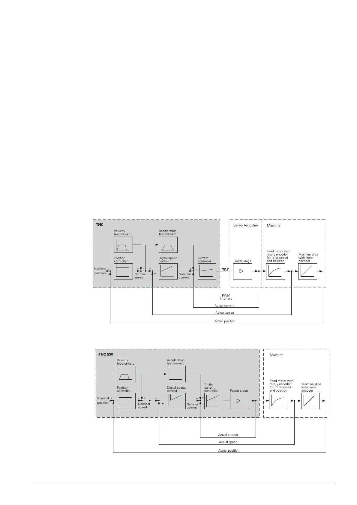
The position, speed and current controllers are integrated in the iTNC 530 HSCI control.
The power output stage is driven over PWM signals.
PWM is the abbreviation of pulse-width modulation. The information content in this signal is the ratio
of pulse duration and pause duration.
Figure: Simplified representation of cascade control for the digital control loop with a modular inverter
system
Figure: Simplified representation of cascade control for the digital control loop with a UEC 11x compact
controller

 Loading...


