February 2012 26 – 431
26.6 Error diagnosis on the laser touch probe
Control impaired? If you suspect that a damaged laser system or a laser system into which liquid has penetrated impairs
the function of the control:
8 Disconnect the laser system and observe the reaction.
--> See ”Deselecting and disconnecting the touch probe” on page 26 – 433.
Visual inspection
8 Check whether the laser system or the cable is damaged, etc.
8 Is the pressure of the compressed air unit correct (read the display)?
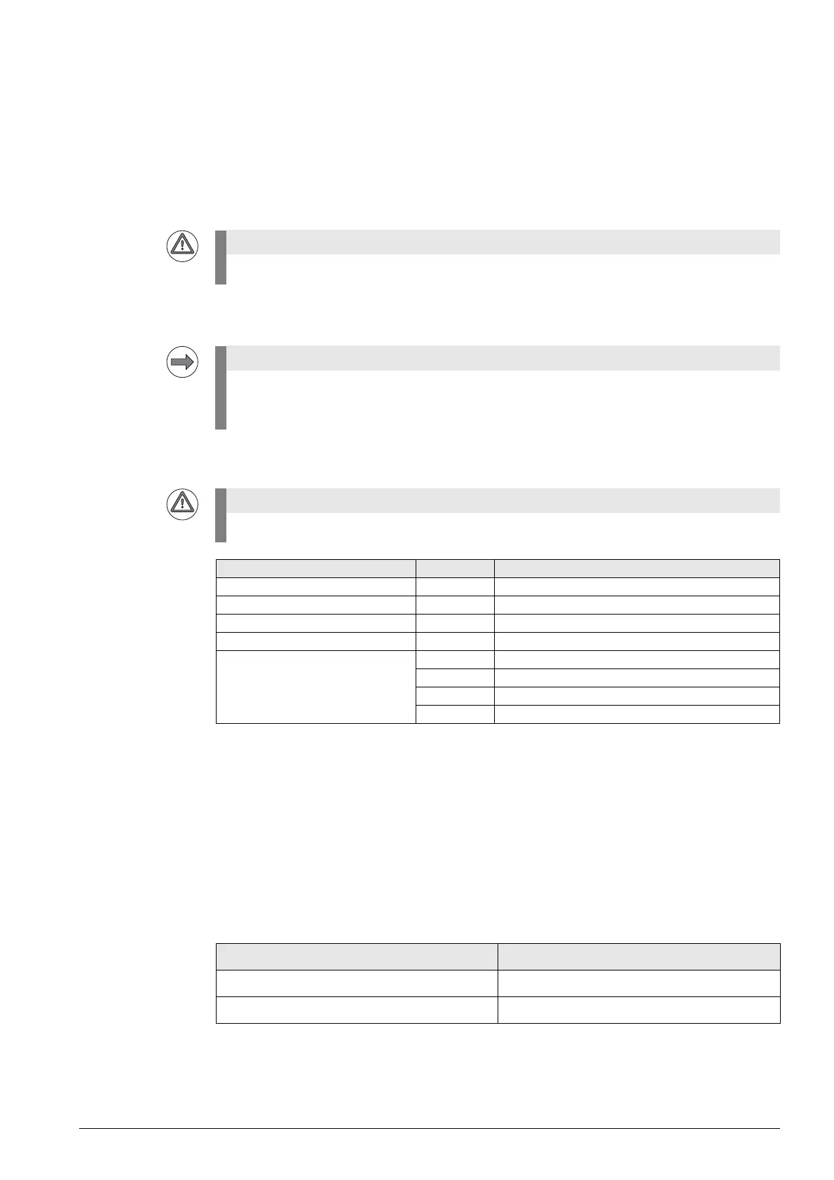
Checking the LEDs
Checking the
Ready bridge
In the laser touch probe the Ready signal is bridged.
This means that the Ready signal must always be present when a laser touch probe is connected.
Proceed as follows to check the Ready bridge:
8 Shut down the control and switch off the machine.
8 Disconnect the touch probe cable (possibly together with the adapter ID 667674-01) from the
connector X113 of the UEC 11x controller unit or the PL 62xx system module.
8 Use a multimeter which you set to "beep" mode or to ohm measurement.
8 Apply the needle tips to the following pins of the touch probe cable:
8 A beep must be heard or a low ohmic value displayed.
Laser radiation! Do not stare into beam! Laser class 2.
For descriptions of the wiring, status displays and maintenance (e.g. cleaning and lubrication of
components, functional check of the shutter) refer to the mounting instructions of the laser touch
probe.
Laser radiation! Do not stare into beam! Laser class 2.
Optical status indicator LED Function
Laser ON Green Input for enabling transmission
Alignment Green Laser adjustment OK (signal > 95 %)
Laser OK Green Laser output OK (signal > 75 %)
Output Red DYN output (signal > 50 %)
Mode White Operating mode 0
Green Operating mode 1
Red Operating mode 2
Yellow Operating mode 3
Laser touch probe, cable Pins to be contacted
Without touch probe adapter ID 667674-01 10 (+ 24 V NC) and 3 (TT is ready)
With touch probe adapter ID 667674-01 10 (+ 24 V NC) and 3 (touch probe ready)

 Loading...


