February 2012 28 – 501
28.12.2 Pin layouts
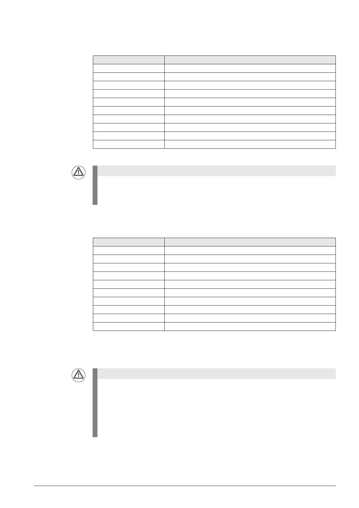
X6:
PLC inputs
X7:
PLC outputs
Current load of the outputs: Maximum 150 mA per output
Connecting terminals Assignment
1I0
2I1
3 I2 (Control Voltage ON, CVO)
a
a. With standard wiring
4I3
5I4
6I5
7I6
8I7
9 Reserved (do not assign)
10 Reserved (do not assign)
Please note that the MB 620 is powered by +24 V NC.
For the entire HSCI system, the +24 V NC power supply voltage is required to be safely separated
voltage. It must also be safely separated from the +24 V PLC!
Connecting terminals Assignment
1 O0 (illumination for the NC Start key)
a
a. With standard wiring
2 O1 (illumination for the NC Stop key)
a
3 O2 (illumination for the Control Voltage ON key)
a
4O3
5O4
6O5
7O6
8O7
9 +24 V NC (available here)
10 0 V NC (available here)
Please note that the outputs of connector X7 are powered internally by +24 V NC, and therefore
supply +24 V NC at HIGH level.
For the entire HSCI system, the +24 V NC supply voltage is required to be safely separated
voltage. The +24 V NC supply voltage must not, under any circumstances, be connected with the
+24 V PLC supply voltage, because this removes the double basic insulation.
Each of the switching outputs at X7 supplies up to 150 mA of output current and are provided for
driving the lamps on the MP620.

 Loading...


