D2 Drive User Guide v1.8 5. Drive Configuration
HIWIN Mikrosystem Corp. 106
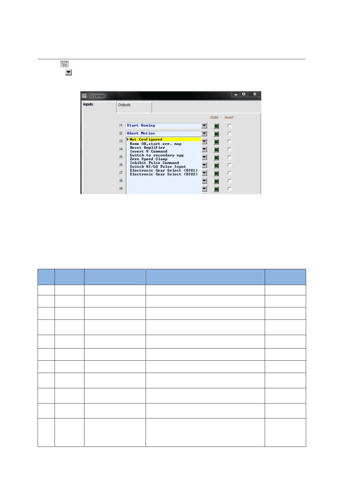
5.5. I/O center
5.5.1. Digital input
Click in the main toolbar on the main window to open the I/O center. Click the drop-down
button ( ) in the input function menu to select the digital input pin and its function, as shown
in Fig. 5-40. D2 (D2T) model has 9 (10) digital inputs.
Fig. 5-40 Input function menu
(1) Status indicator light
If the status indicator light is green, it means that the corresponding input pin has been
activated. If the light does not light, it means that the input pin is not activated.
(2) Logic inverse setting (Invert)
When the “Invert” option is checked, the trigger condition will be reversed.
Table 5-5
Enable/Disable; the default used in I3.
Left hardware limit; the default used in I6.
Right hardware limit; the default used in I9.
The homing completed command from the
host controller.
Reversing the analog voltage command in the
velocity or force/torque mode.
Switching to secondary common gain.
Switching to secondary vpg gain.
Zero speed clamp. In the velocity mode, the
motor will be locked in a fixed position when
the drive receives this signal and the motor
speed is less than the set value.
 Loading...
