D2 Drive User Guide v1.8 6. Drive Tuning
HIWIN Mikrosystem Corp. 167
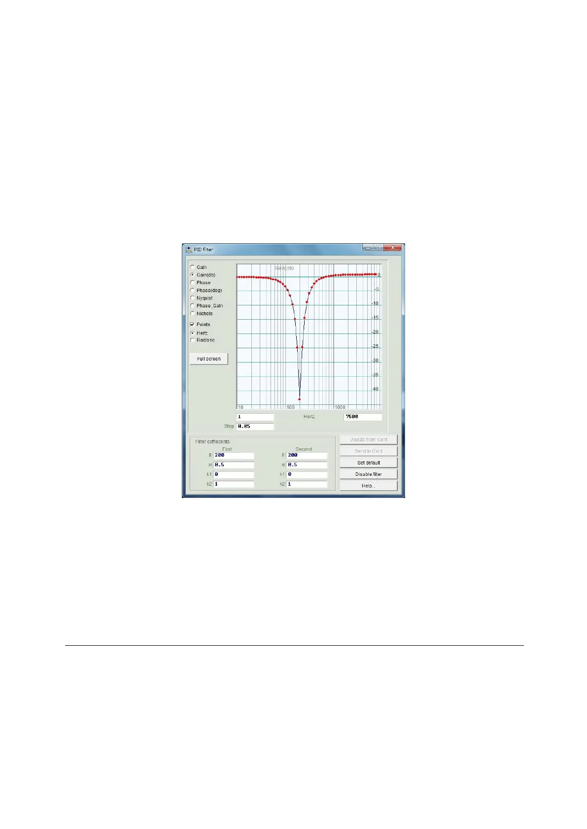
(2) Notch Filter
When the system has an inappropriate resonance frequency (for example, between 10
and 250 Hz) that cannot be eliminated by the mechanism correction or design
enhancement, the notch filter can be used to improve this problem. In general, the notch
filter should be set according to the result of frequency analysis. Refer to Section 6.6.3.
The setting of typical notch filter is given as follows:
○1 fr: The cutoff frequency of filter. The unit is Hz.
○2 xi: The damping ratio of filter. Its value ranges from 0 to 1. The closer to 0 this value is,
the narrower the filtering frequency band is; while the closer to 1 this value is, the
wider the filtering frequency band is.
○3 k1: 0.
○4 k2: 1.
Fig. 6-26 Notch filter
(3) Automatic resonance suppression filter (f3)
After the auto gain tuning is successful, the automatic resonance suppression filter (f3)
will be set and started automatically. However, after the auto gain tuning is completed,
when the system vibration cannot be effectively suppressed by the f3 filter at driving the
motor, cancel the check of “Activate f3” option in the “Filter” tab of “Advanced gains”
window, as shown in the red box of Fig. 6-24. Then, modify “Filter 1” and “Filter 2” in
manual to achieve an effective vibration suppression.
6.6.2. Acceleration feed-forward
The position error of servo control is usually large in the motion phase of acceleration or
deceleration. Especially for applications with a large moving mass or moment of inertial, this
problem is more likely to occur. By setting the parameter of acceleration feed-forward, the
position error can be reduced effectively in the acceleration/deceleration phase.
Following steps are used to adjust the acceleration feed-forward.
Step 1. Click the “Set scope…” button to display the “Scope” window.
Step 2. Set “Acc feedforward gain” in Fig. 6-27 to 0.
Step 3. Set the maximum acceleration for path planning, and let the motor do the
 Loading...
