D2 Drive User Guide v1.8 5. Drive Configuration
HIWIN Mikrosystem Corp. 117
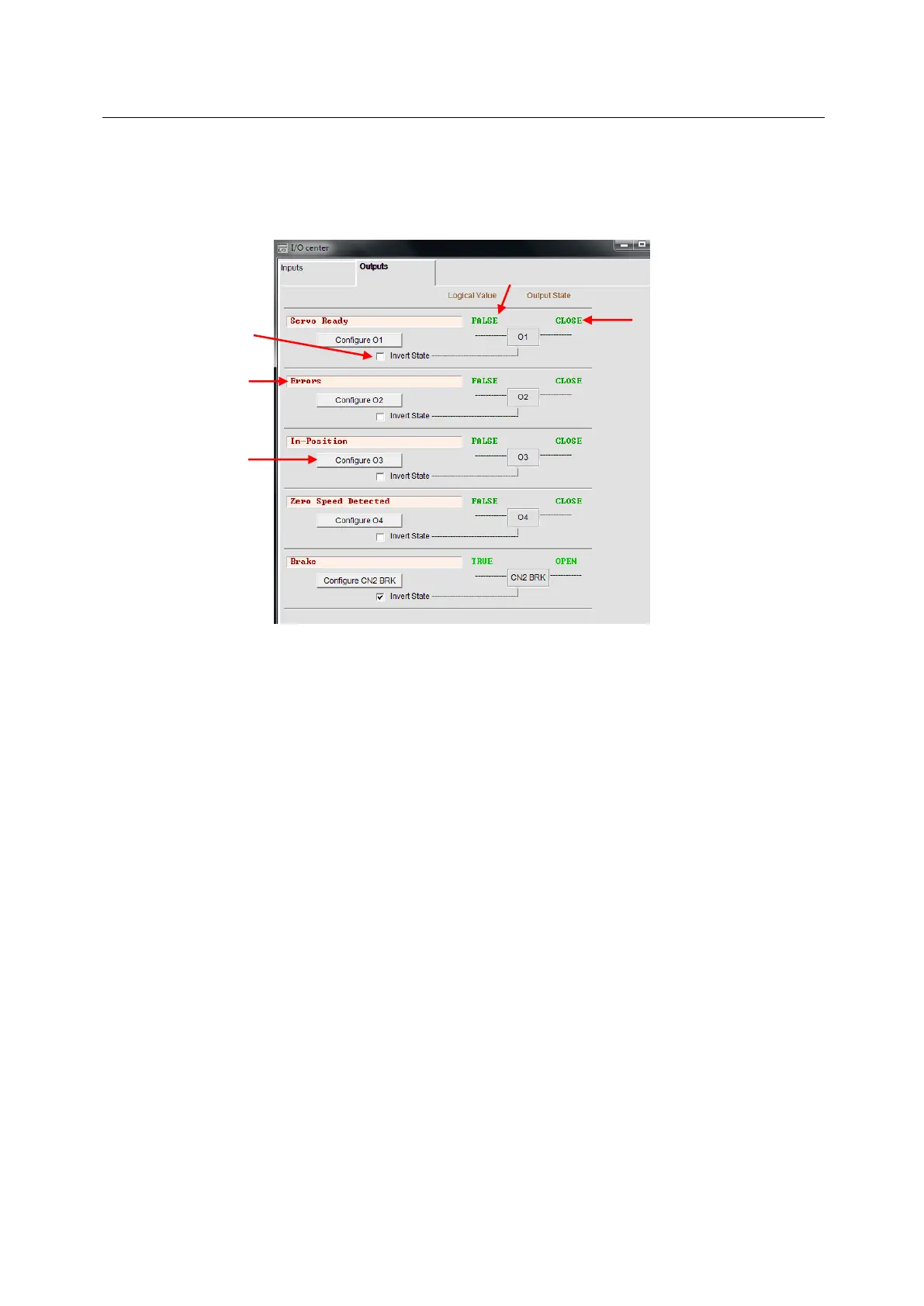
5.5.2. Digital output
D2 model provides 5 sets of programmable digital output. Here, 4 sets (O1 - O4) are general-
purpose outputs located on the CN6 connector. The fifth set (CN2 BRK) is specially designed
as the brake output and can also be used as the general-purpose output. D2T model has
more than one general-purpose output (O5) located on the CN6 connector. In this section,
take D2 model as an example to illustrate the digital output function.
Fig. 5-41 Digital output
(1) Logical value
The logical value of each output signal is displayed here. The displayed value is TRUE or
FALSE.
(2) Output function
When any item in the function menu on “Configuration” window is checked, the item name
is shown in the status display field. If two or more items are checked, it shows
“Customized”. If all error items are checked, as shown in Fig. 5-41, it shows “Errors”. If no
item is checked, it shows “PDL usage (General Purpose)” for the usage of general-
purpose output. This means that the output function is controlled by the PDL program
language.
(3) Output state
The current state of drive output pin is displayed here to be CLOSE or OPEN (transistor is
conducted or not conducted). This allows to know the state of hardware signal on the
drive output to assist in wiring debugging.
(4) Invert state
If required, this option can be checked to reverse the polarity of output state to match the
host controller.
Note: The internal logic of drive is not affected by this “Invert State” setting at all.
(5) Output function setting
Each output pin has one corresponding “Configure” setting button. Taking O1 as an
example, click the “Configure O1” button to open the “Configuration” window. This menu
can be divided into three categories: “Statuses”, “Errors”, and “Warnings”, as shown in
Fig. 5-42. If two or more items are selected in the same configuration category, the output
function works when one of these items is triggered. If all checked options need to be
 Loading...
