D2 Drive User Guide v1.8 4. Wiring
HIWIN Mikrosystem Corp. 63
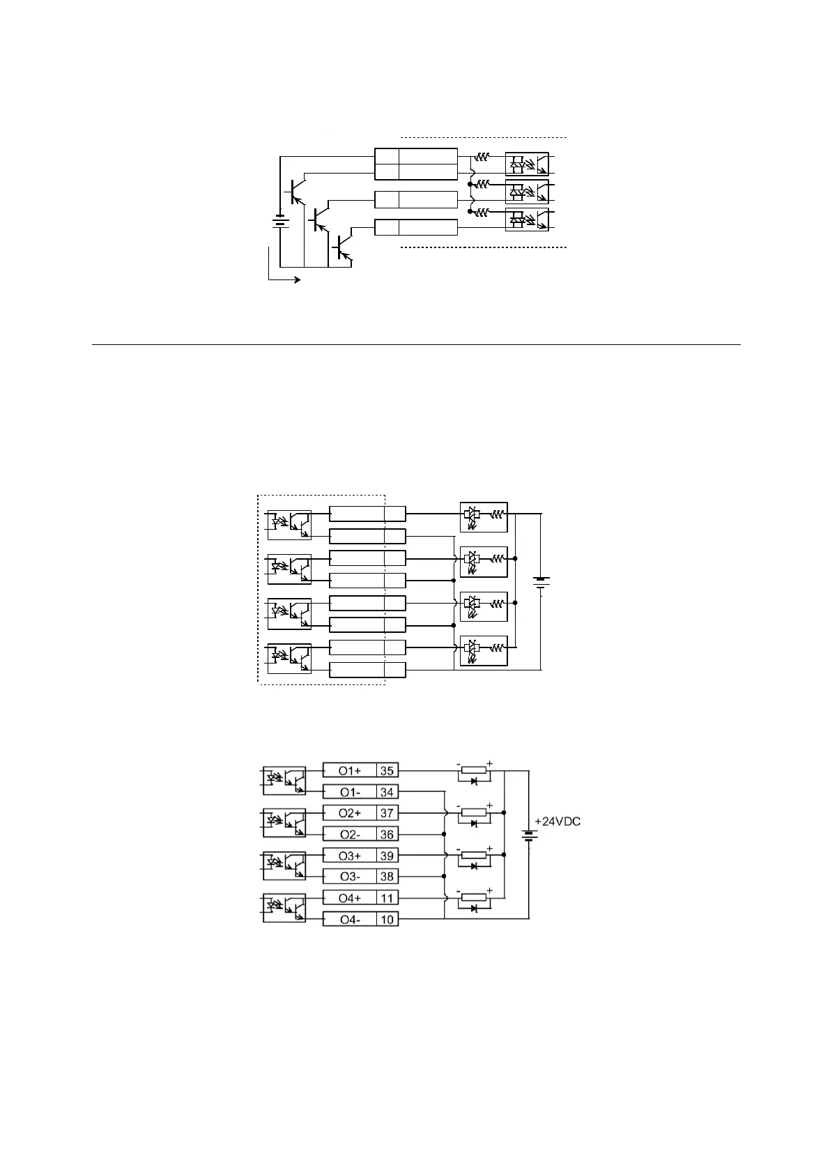
(2) Input wiring example via transistors:
Fig. 4-28
4.5.2. Digital output wiring
General-purpose outputs of D2-series drive adopt the output interface of optical-coupler
Darlington suitable for the voltage system of less than 24 Vdc. D2 (D2T) model has 4 (5)
general-purpose outputs. Each output has an independent Darlington open-collector circuit.
The maximum allowable current is 100 mA. Users can configure the function of each output
by using the software.
Note. When O5 of frame D model is set to brake signal output, it is necessary to connect to a
relay to control the motor brake, since its maximum allowable current is 100 mA.
Fig. 4-29
(1) Output wiring example via relays
Fig. 4-30
COM7
I1
I2
I3
4.7K
33
30
29
Source接法
COM7
I1
I2
I3
4.7K
33
30
29
Source接法
電流 電流
O1+ 35
O1- 34
O2+ 37
O2- 36
O3+ 39
O3- 38
O4+ 11
O4- 10
+-
+-
+-
+-
+24VDC
O1+ 35
O1- 34
O2+ 37
O2- 36
O3+ 39
O3- 38
O4+ 11
O4- 10
+24VDC
 Loading...
