D2 Drive User Guide v1.8 6. Drive Tuning
HIWIN Mikrosystem Corp. 181
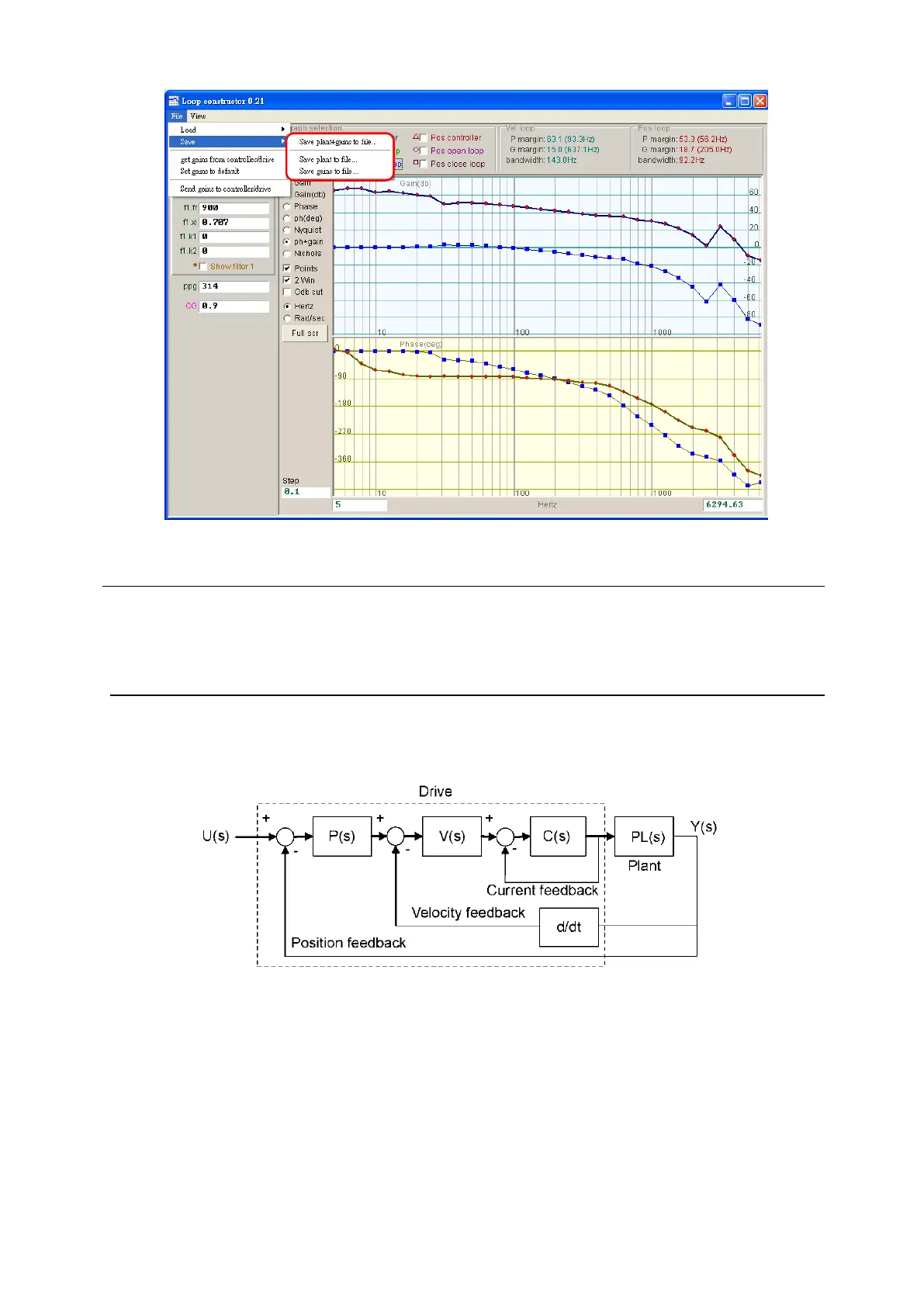
Fig. 6-50 Loop constructor - save data to file
6.7.2. Tool
Spectrum analysis tools of “Loop constructor” can analyze and simulate the Nyquist, Bode,
and Nichols diagrams of control system. By using this function, the frequency response of
control system can be obtained.
6.7.2.1. Frequency response function
The frequency response can be expressed by the transfer function of dynamic system, which
indicates the relative relationship between the input signal and the output signal of dynamic
system. The control architecture of drive is shown in Fig. 6-51.
Fig. 6-51 Control structure of the drive
- U (s): System input. It is the drive command.
- Y (s): System output. It is the position feedback of encoder.
- Plant: PL(s) is the relationship between the drive command and the feedback position.
The plant contains the mechanical platform, motor, and feedback system.
- Controller: P(s) is the position loop controller, V(s) is the velocity loop controller, and C(s)
is the current loop controller.
- Open loop: The transfer function of open loop system is “G(s) =P(s)*V(s)*C(s)*PL(s)”,
meaning to ignore all feedback signals.
- Close loop: The transfer function of close loop system is
T(s) = P(s)*V(s)*C(s)*PL(s)/((d/dt*P(s)*V(s)*C(s)*PL)+P(s)*V(s)*C(s)*PL(s)).
 Loading...
