D2 Drive User Guide v1.8 4. Wiring
HIWIN Mikrosystem Corp. 62
4.5. I/O signal wiring
D2 model provides 9 general-purpose inputs and 4 general-purpose outputs on CN6
connector; while D2T model provides 10 general-purpose inputs and 5 general-purpose
outputs on CN6 connector. Users can configure the function of each I/O by using the software.
In this section, take D2 model as an example. The wiring method for D2T model is the same
as that for D2 model.
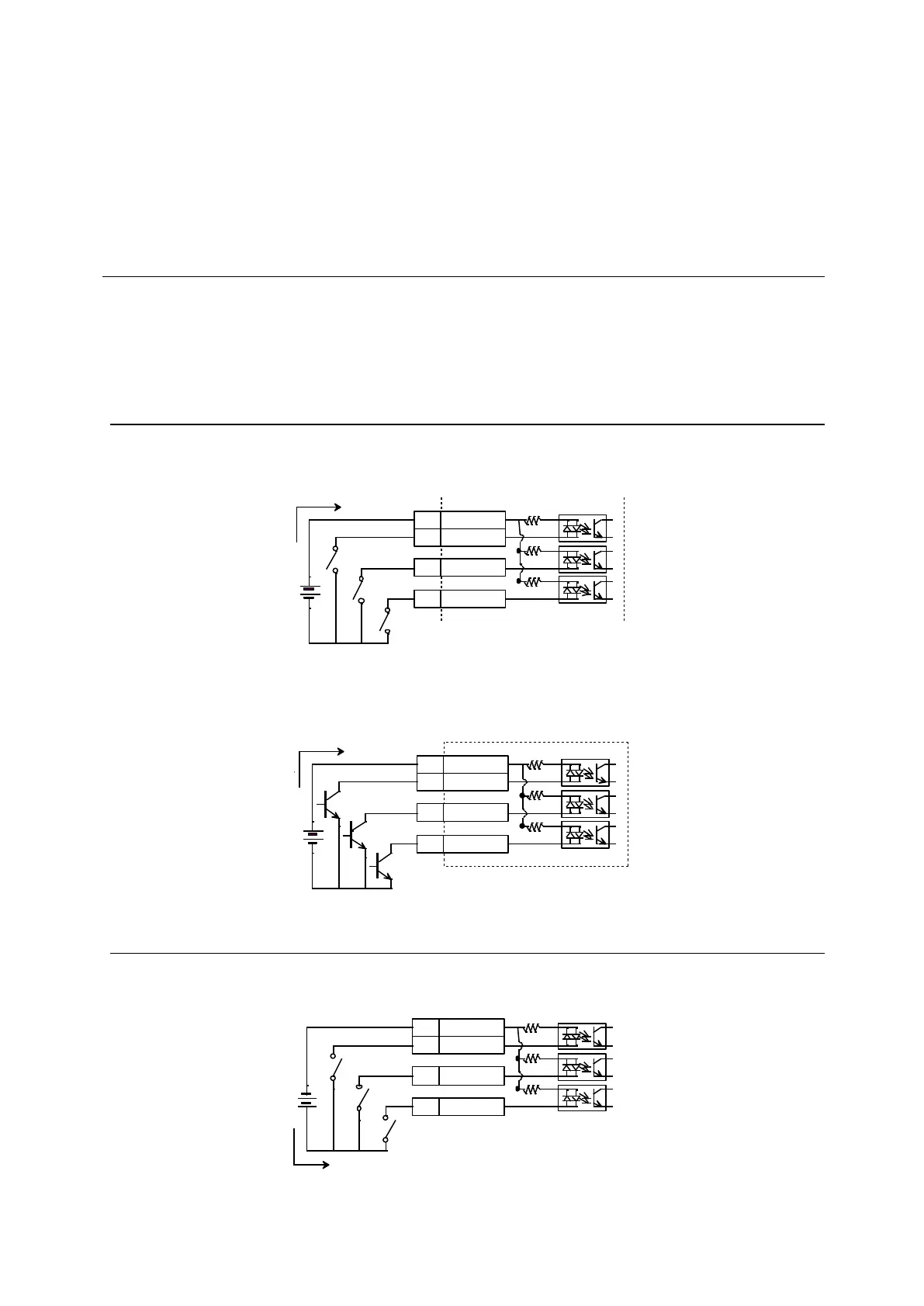
4.5.1. Digital input wiring
General-purpose inputs of D2-series drives adopt the optical-coupler input interface suitable
for the voltage system of 12 - 24 Vdc. D2 (D2T) model has the total of 9 (10) general-purpose
inputs with one COM port and suitable for Sink or Source connection at the same time. The
default function of I3 is “Axis Enable”. Others can be set by using the human-machine
interface (HMI) based on the user’s requirement.
4.5.1.1. Sink input wiring examples
(1) Input wiring example via switches or relays:
Fig. 4-25
(2) Input wiring example via transistors:
Fig. 4-26
4.5.1.2. Source input wiring examples
(1) Input wiring example via switches or relays:
Fig. 4-27
COM7
I1
I2
I3
4.7K
33
30
29
Sink接法
COM7
I1
I2
I3
4.7K
33
30
29
Sink接法
電流 電流
COM7
I1
I2
I3
4.7K
33
30
29
Sink接法
COM7
I1
I2
I3
4.7K
33
30
29
Sink接法
電流 電流
COM7
I1
I2
I3
4.7K
33
30
29
Source接法
COM7
I1
I2
I3
4.7K
33
30
29
Source接法
電流 電流
 Loading...
