D2 Drive User Guide v1.8 6. Drive Tuning
HIWIN Mikrosystem Corp. 188
6.9. Error map function
The motor accuracy is usually determined by the linear encoder used on the positioning
platform. The positioning accuracy is usually measured and corrected by using a laser
interferometer, so that the positioning error table can be obtained. D2 drive has an error map
function. By inputting and saving the error table to the drive via HMI, the drive can use this
information to calculate the compensation value at the fixed distance by using the linear
interpolation manner to improve the positioning accuracy.
After measuring the positioning accuracy and obtaining the error table, set the compensation
interval (“Interval”) and total compensation points (“Total points”) first, and then input the error
compensation value into the table one by one.
Note 1. “Error map” takes the home position as the start position, and compensates the
position in the positive direction. Therefore, complete the homing procedure before
enabling the error map function.
Note 2. When the host controller needs to receive the feedback pulse outputted from the
drive, and also to enable the error map function, set “Encoder output” in the “Encoder”
tab to “Use emulated encoder”.
6.9.1. Set error map
The following describes steps of enabling the error map function for D2 drive.
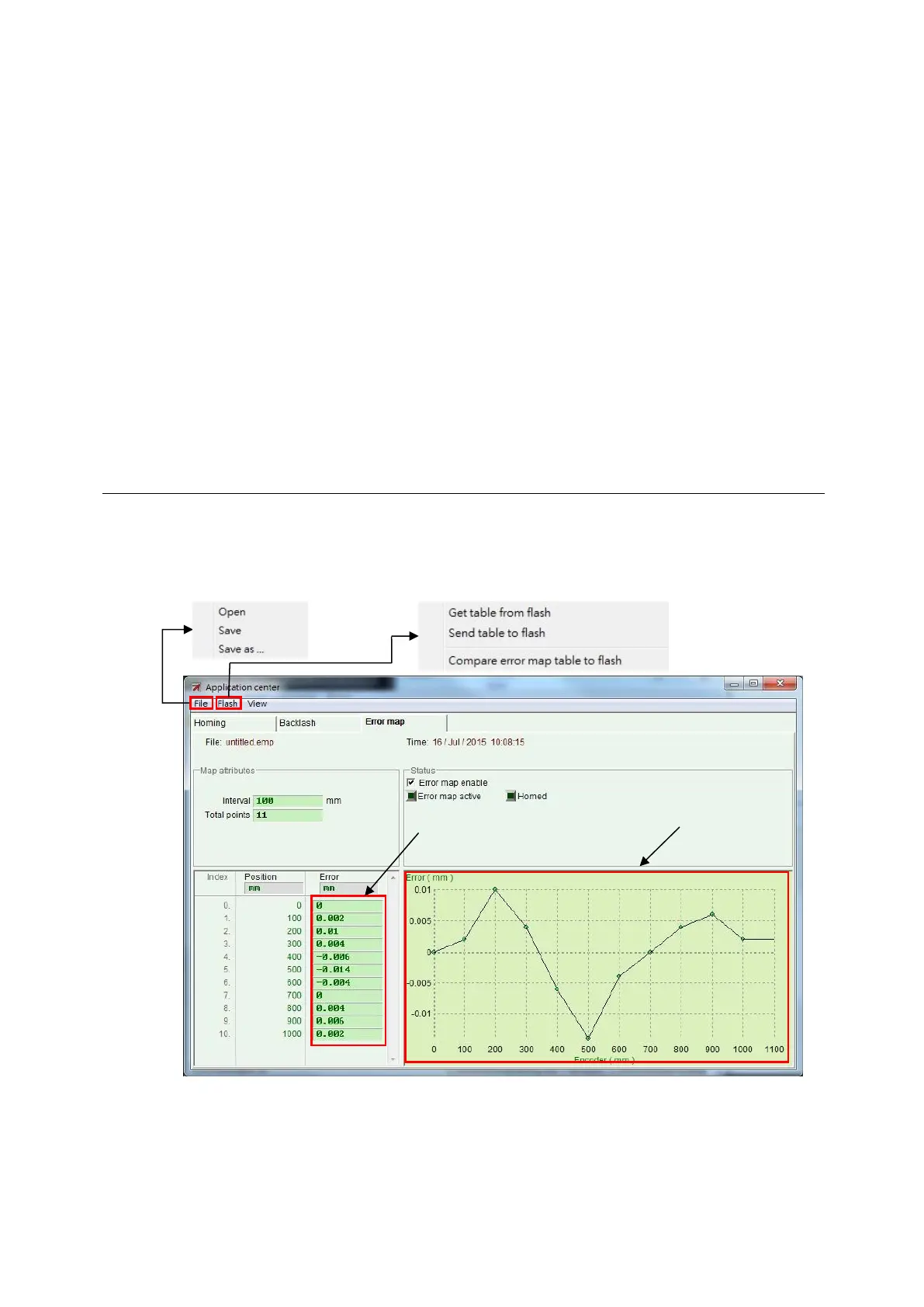
Step 1. Go to the application center and select the “Error Map” tab to open the window of
error map function, as shown in Fig. 6-60.
Fig. 6-60 Error map window
Step 2. Set the compensation interval (“Interval”) and total compensation points (“Total
points”), and then enter the error compensation value into the “Error” field. If a
different custom unit is needed, click the unit field to set different unit. Taking the
example of Fig. 6-61, the compensation range is from 0 to 1,000 mm, the
compensation interval is 100 mm, and the total compensation point is 11 points. The
Error compensation
value for each position
send to
compensation
save
file
 Loading...
