D2 Drive User Guide v1.8 6. Drive Tuning
HIWIN Mikrosystem Corp. 184
6.7.3. Filter
The control loop of drive provides two filters, which can be used at the same time. They are
designed to suppress the high-frequency noise, machine vibration, shortage structure rigidity,
and so on.
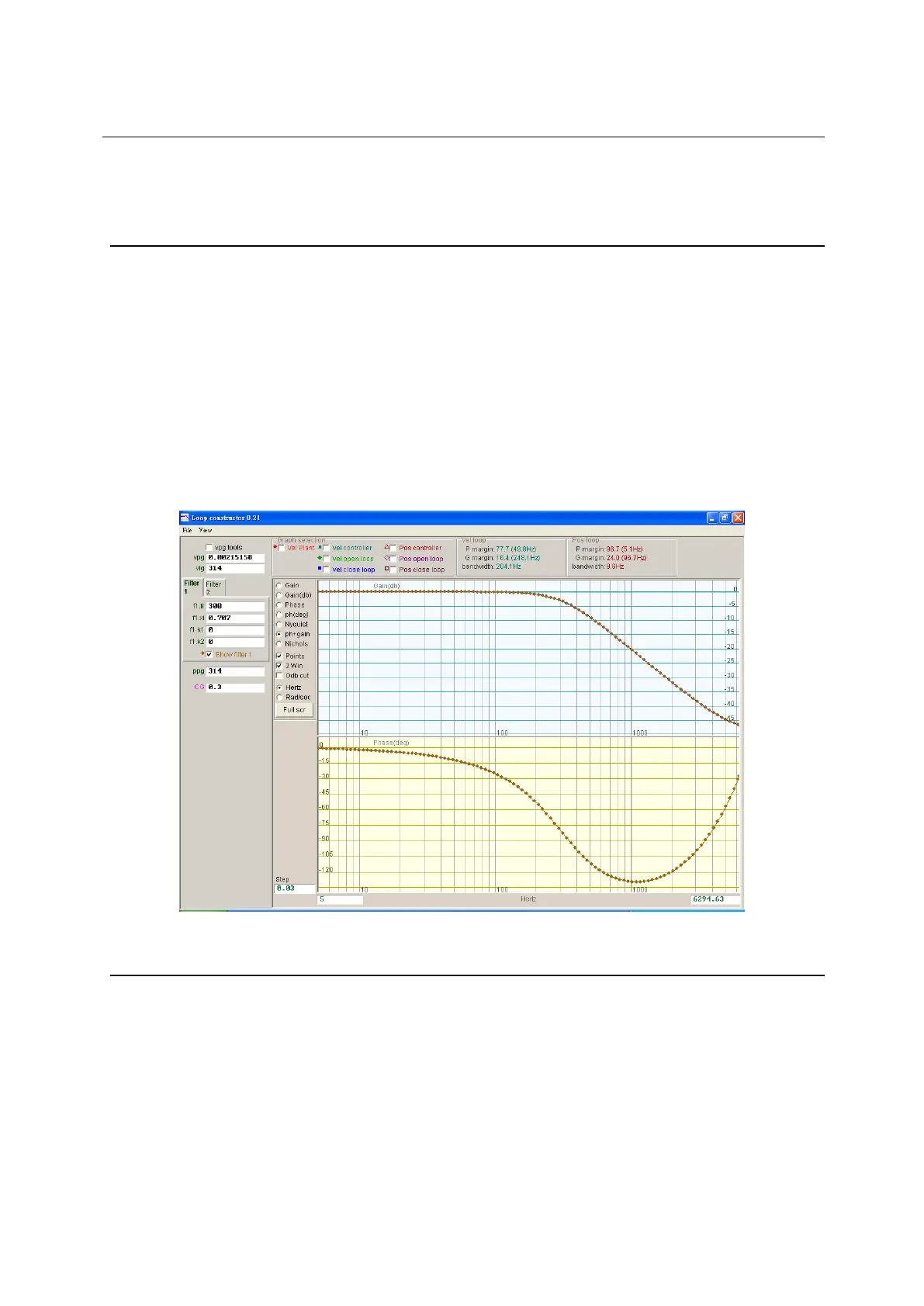
6.7.3.1. Low pass filter
The low pass filter in the control system is used to suppress the high-frequency noise or
machine vibration. The Bode plot of low pass filter is given in Fig. 6-55. Modifying the filter
parameters (fr, xi) will affect the frequency response of various control loop analysis. This is
used to simulate the frequency response of control system plus low pass filter to facilitate the
actual adjustment.
(1) fr: The cutoff frequency of filter. The unit is Hz. For general applications, a good effect
can be achieved at the setting of 500 Hz. Other cases can be considered to
decrease this value. However, the control performance will be reduced if the cutoff
frequency is too small.
(2) xi: The damping ratio of filter. Its value ranges from 0 to 1.
(3) k1: Low pass filter = 0.
(4) k2: Low pass filter = 0.
Fig. 6-55 Low pass filter
6.7.3.2. Notch filter
When the mechanism system has an inappropriate resonance frequency and the resonance
phenomenon cannot be eliminated by modifying the design of mechanism, this problem can
be improved by using a notch filter. The Bode plot of notch filter is given in Fig. 6-56. Modifying
the filter parameters (fr, xi) will affect the frequency response of various control loop analysis.
This is used to simulate the frequency response of control system plus notch filter to facilitate
the actual adjustment.
(1) fr: The cutoff frequency of filter. The unit is Hz.
(2) xi: The damping ratio of filter. Its value ranges from 0 to 1. The closer to 0 the narrower
the filtering frequency band is, the closer to 1 the wider the filtering frequency band
is.
(3) k1: Notch filter = 0
 Loading...
