D2 Drive User Guide v1.8 3. Operation Principles
HIWIN Mikrosystem Corp. 30
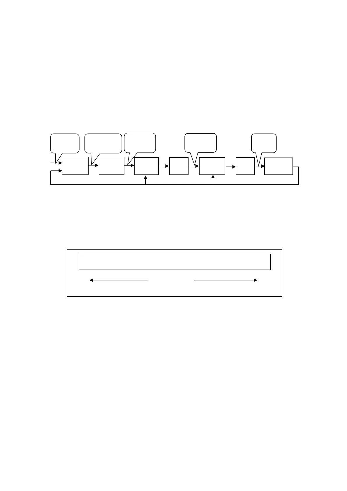
3.5. Servo loops and gains
(1) Servo loops
There are three types of control loop for D2 drive: current, velocity, and position control
loops to implement the servo motor control. The architecture of drive’s servo loop is
described in Fig. 3-6. In the position mode, three loops should be connected in sequence
to perform the position control for the motor. In the velocity mode, the velocity loop should
use the current loop to drive the motor. However, in the current mode, the current loop
only controls the phase commutation mechanism of motor, and its command is controlled
by the voltage command from the host controller. To simplify gain parameters of servo
loops, D2 drive only uses one common gain (CG) to set and adjust the overall
control-loop architecture.
Fig. 3-6
(2) Servo gains
D2 drive uses one high-speed DSP to implement the motor control. Generally, when the
servo loop is implemented by the digital method, it needs to adjust many servo gains.
However, this drive adopts an ingenious control design to simplify servo gains as one
common gain to significantly improve convenience.
Fig. 3-7
0.1
……………………………………
5
……………………………………
1