D2 Drive User Guide v1.8 4. Wiring
HIWIN Mikrosystem Corp. 49
Table 4-5
RS485 Modbus communication
(2) Frame D
Connector model: TE Connectivity 2040008-1 (female).
Fig. 4-16
Table 4-6
RS485 Modbus communication 1
RS485 Modbus communication 2
4.1.6. CN5 Modbus communication/safety function
CN5 connectors of frame A-C models are Modbus communication ports; while the CN5
connector of frame D model is the input of safety-function device. Check the pin assignment
for each model before use.
(1) Frame A-C
They are Modbus communication ports. Refer to Section 4.1.5.
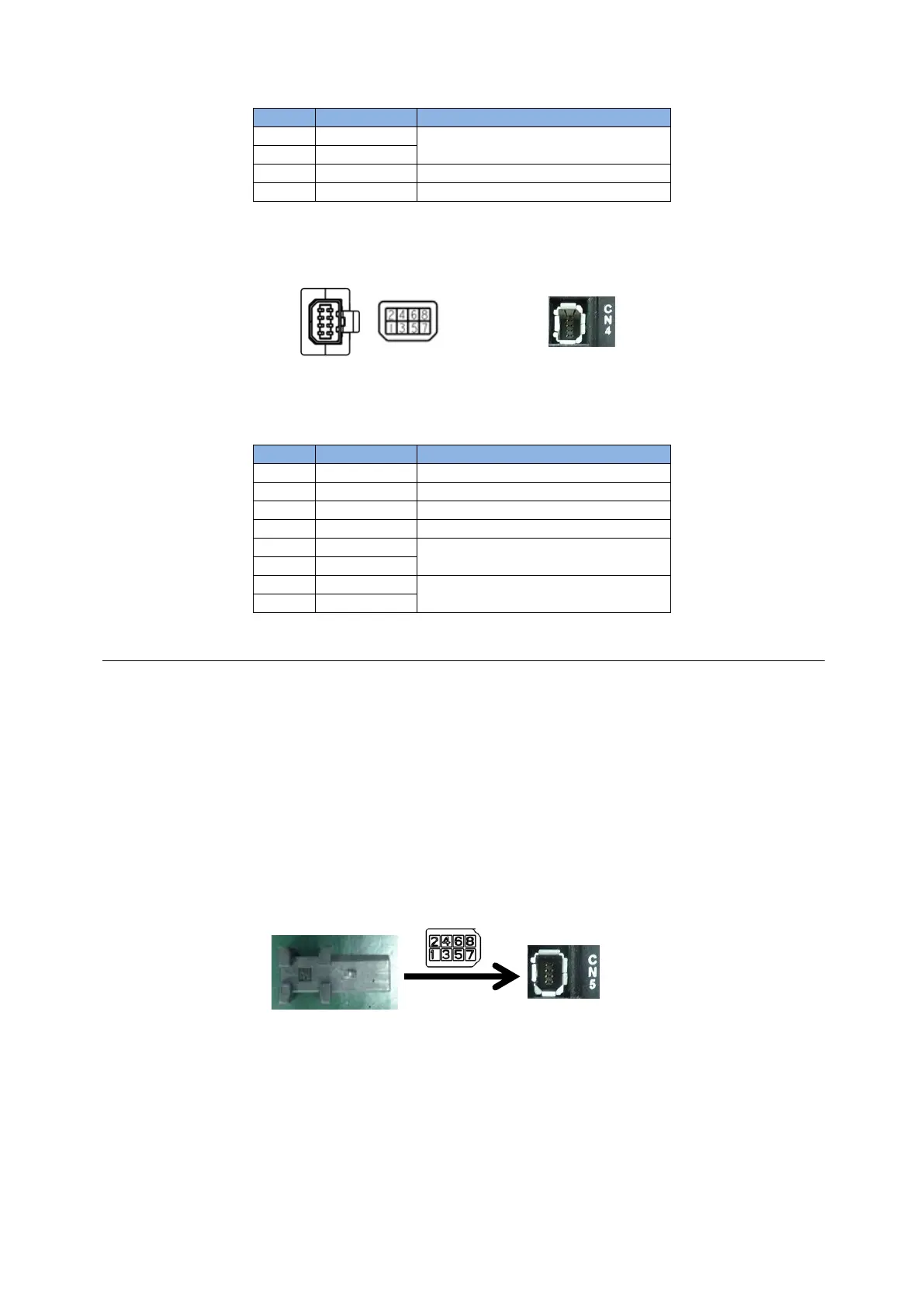
(2) Frame D
If the safety function is not used, connect the supplied safety jumper to CN5. When the
safety jumper is not installed, the drive will not supply current to the motor, and the motor
will not work normally.
Connector model: TE Connectivity 1971153-1 (female).
Fig. 4-17
(a) RS485 (female connector)
(b) RS485 (male connector)
 Loading...
