D2 Drive User Guide v1.8 3. Operation Principles
HIWIN Mikrosystem Corp. 31
3.6. Gain margin and phase margin
3.6.1. Nyquist diagram
Gain margin (GM) is defined as that the loop gain, calculated by dB, can be increased before
the close-loop system becomes unstable. On the other hand, phase margin (PM) is defined as
that the phase delay can be increased before the close-loop system becomes unstable.
(1) Gain margin:
Denote G(jω
p
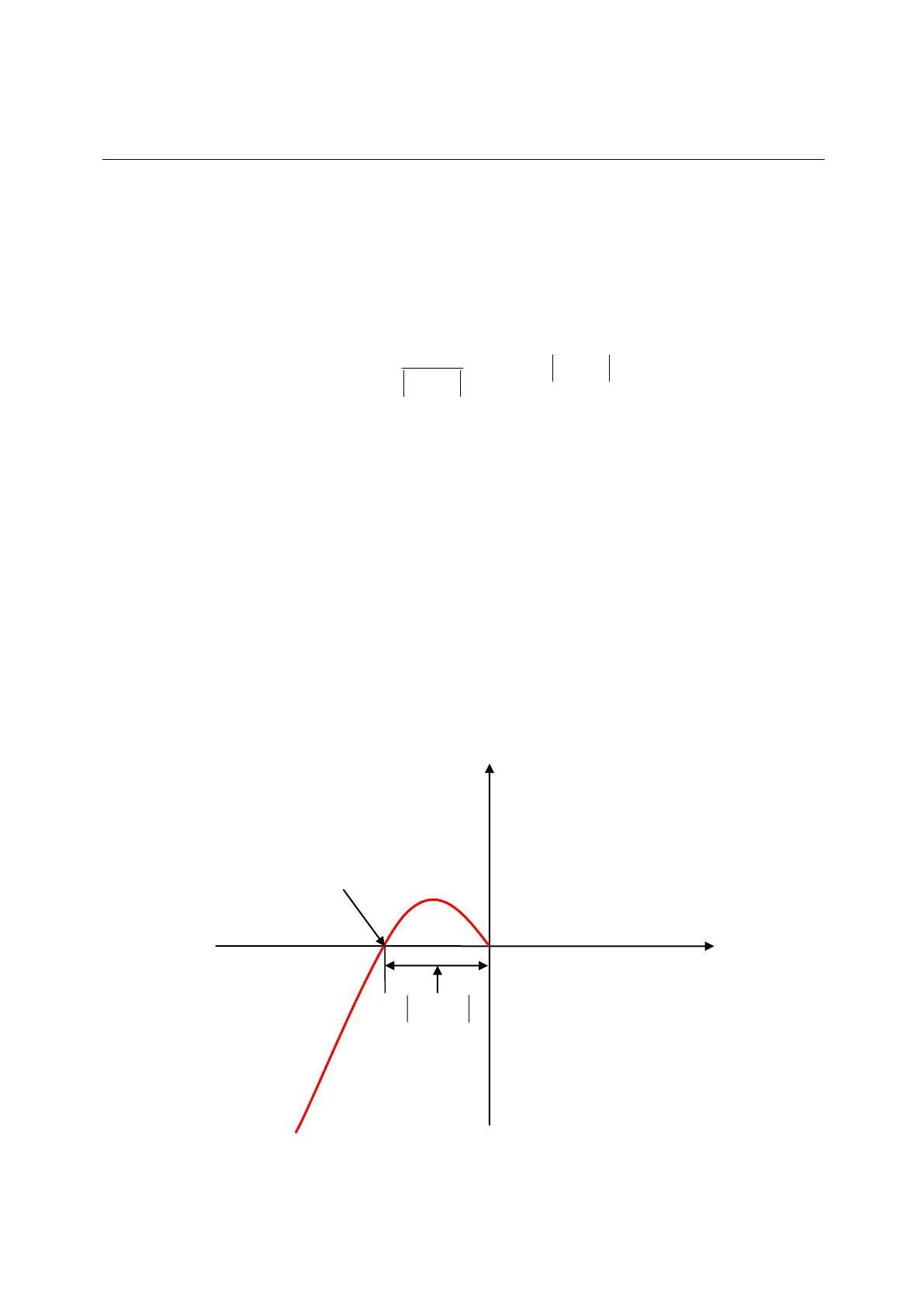
) as the relative distance from the intersection of Nyquist diagram and the
negative real axis to the point (-1, j0), where ω
p
is the frequency at the phase crossover.
The example of G(jω
p
) = 180° is shown in Fig. 3-8. For the transfer function G(s) in a
loop system,
gain margin = GM = dB.
Following results can be derived from Fig. 3-8 and characteristics of Nyquist diagram.
a. If G(jω) does not intersect with the negative real axis, |G(jω
p
)| = 0 and GM = dB.
When the Nyquist diagram does not intersect with the negative real axis at any
non-zero and finite frequency, GM = dB. Theoretically, the loop gain can be
increased to be infinite before the system becomes unstable.
b. If G(jω) intersects with the negative real axis between 0 and -1, 0 < |G(jω
p
)| < 1 and
GM > 0 dB. When the Nyquist diagram intersects with the negative real axis between
0 and -1 at any frequency, the system is stable as increasing loop gain.
c. If G(jω) is at the point (-1, j0), |G(jω
p
)| = 1 and GM = 0 dB. When the Nyquist diagram
G(jω) is at the point (-1, j0), GM = 0 dB. This means that the system reaches the
unstable boundary and the loop gain cannot be increased any more.
d. If G(jω) passes by the point (-1, j0), |G(jω
p
)| > 1 and GM < 0 dB. When the Nyquist
diagram G(jω) passes by the point (-1, j0), GM < 0 dB. At this time, GM must be
reduced to achieve the steady state of loop gain.
Fig. 3-8 Gain margin of Nyquist diagram
)(log
)(
log
p
p
jG
jG
1010
20
1
20
 Loading...
