D2 Drive User Guide v1.8 7. LCD Operation
HIWIN Mikrosystem Corp. 198
7.1. LCD function
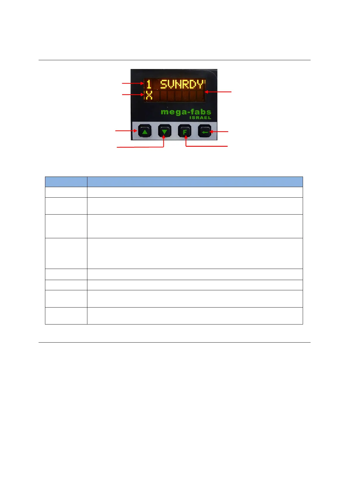
7.1.1. Panel description
Fig. 7-1 LCD panel
Table 7-1 Panel function description
Display change parameter values, statuses, parameters, actions, and so on.
LCD display is divided into four pages. The current page number is shown in the
upper left corner.
The axis name is displayed on the first page - home page, and can be modified on
the HMI main window. Refer to Section 5.1.3. Messages will also be displayed if
there are errors or warnings.
- Static cursor: Flashing underscore. The parameter can be edited.
- Dynamic cursor: Solid flashing box cursor. The parameter is editing or the
continuous motion is in progress (jogging).
- No cursor: Parameters can only be displayed, but not edited.
Select options, set parameter values, and do “Jog” action.
Select options, set parameter values, and do “Jog” action.
Switch among four modes, and switch between actions of edit mode at setting the
parameter value.
Enter the option of status display, save the setting parameter value, and confirm
the action input.
7.1.2. Operation page description
There are four modes on the display panel: home page, display parameters page, change
parameters page, and actions page. Press the F key to switch to other mode. The overall
structure of LCD is shown in Fig. 7-2.
(1) Home page
It mainly shows the servo enable state of drive, error message or warning message, and
the axis name of servo axis.
(2) Display parameters page
It mainly shows the motor feedback position, reference position, position error, feedback
velocity, reference velocity, I/O statuses, motor statuses (phase initialization, motor
movement, homing, error map), and other parameters.
(3) Change parameters page
It mainly is used to change the common gain, velocity loop gain, phase initialization gain,
 Loading...
