D2 Drive User Guide v1.8 8. Protection Function
HIWIN Mikrosystem Corp. 238
8.3. Brake output
In order to protect the motor and the system structure, D2-series drives provide a brake signal
output to actuate an external electromagnetic brake, which is often used in the Z-direction
motor actuation. There are some timing motion issues in this application. For example, when
the motor moves in the Z direction and the drive receives a disable command, if the brake
directly starts at the high speed, the great shock will be generated to damage the mechanism.
In addition, if the motor is disabled early, there is a risk that the mechanism and the motor may
slip. D2-series drives have proprietary brake parameters to reduce this risk.
Click to enter the protection center and select the “Brake” tab to open the configuration
page for braking timing. The output pin of brake can be set by clicking the “Set…” button on
this page. The default pin is CN2_BRK for frame A - C models and O5 for the frame D model.
Click this button to show the configuration page of I/O center. Refer to Section 5.5.2 for the
setting information.
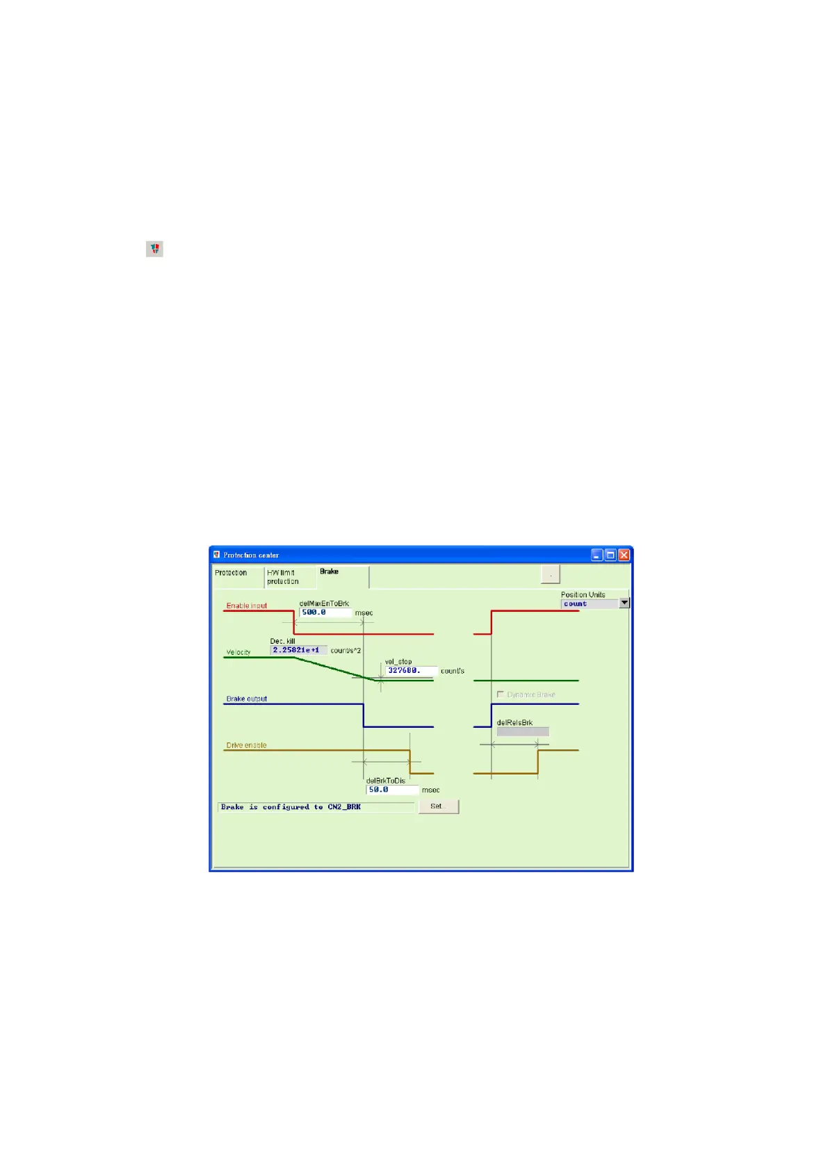
(1) Brake configuration page for frame A - C models
The brake configuration page for frame A - C models is shown in Fig. 8-6. After the drive
receives the hardware input signal or software disable operation, it starts the following
action sequence.
Step 1. When the drive receives the disable command, the brake will be started after the
delay time of starting brake (“delMaxEnToBrk”). However, if the motor speed is
reduced to the brake start speed (“vel_stop”), the brake is started first.
Step 2. Counting from the drive starting the brake, the post-stage power will be turned off
after the set brake action time (“delBrkToDis”). Its main purpose is to completely
and truly execute the brake action.
Fig. 8-6
 Loading...
