Roche Diagnostics
F-10
Operator’s Manual · Version 3.4
13 ISE description Cedex Bio analyzer
Hardware
ISE LED
The ISE LED is color coded.
Main components
Peristaltic pump A fluid pump that draws the solutions through the electrode block and then pumps it
to the internal waste tank.
Input-valve plate A set of valves to create cleaning segments and to control the flow of waste fluids.
Entry-valve plate A set of valves to control and monitor the flow of fluids.
Exit-valve plate A set of valves to control the aspiration action of the peristaltic pump.
Electrode block A block that contains the electrodes.
Power off (e.g. power supply disconnected.)
The ISE unit is OK and ready for use.
Blinking The fluid level in the ISE Reference Solution bottle or ISE Calibrator
indirect is low. Replace the bottle. (Operation has stopped.)
The fluid sensor has detected there is no fluid. Operation has stopped.
Check for the cause of the problem, e.g. no fluid left, blocked ISE tubing,
or fluid transportation problem.
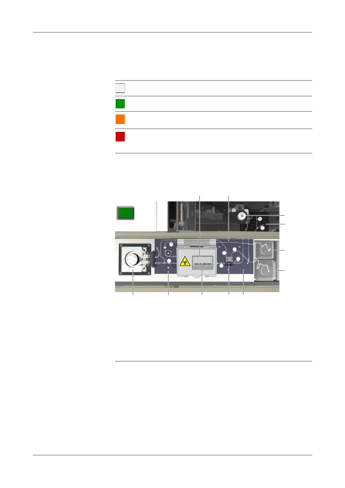
A Electrode block with ISE Sodium, Potassium,
and Reference Electrode
B ISE Reference Solution sensor
C ISE tower
D Input-valve plate
E ISE Reference Solution bottle (red label)
F ISE Calibrator indirect bottle (blue label)
G Peristaltic pump with pump tubing
H Exit-valve plate
I Measuring channel
J ISE sample sensor
K Entry-valve plate with tubing
Figure F-3 Main components of the ISE unit
 Loading...