P
r
o
t
e
c
t
e
d
b
y
c
o
p
y
r
i
g
h
t
.
C
o
p
y
i
n
g
f
o
r
p
r
i
v
a
t
e
o
r
c
o
m
m
e
r
c
i
a
l
p
u
r
p
o
s
e
s
,
i
n
p
a
r
t
o
r
i
n
w
h
o
l
e
,
i
s
n
o
t
p
e
r
m
i
t
t
e
d
u
n
l
e
s
s
a
u
t
h
o
r
i
s
e
d
b
y
V
o
l
k
s
w
a
g
e
n
A
G
.
V
o
l
k
s
w
a
g
e
n
A
G
d
o
e
s
n
o
t
g
u
a
r
a
n
t
e
e
o
r
a
c
c
e
p
t
a
n
y
l
i
a
b
i
l
i
t
y
w
i
t
h
r
e
s
p
e
c
t
t
o
t
h
e
c
o
r
r
e
c
t
n
e
s
s
o
f
i
n
f
o
r
m
a
t
i
o
n
i
n
t
h
i
s
d
o
c
u
m
e
n
t
.
C
o
p
y
r
i
g
h
t
b
y
V
o
l
k
s
w
a
g
e
n
A
G
.
2 Charge Air System
⇒ 2.1 Overview - Charge Air System, page 264 .
⇒ 2.2 Overview - Charge Air Hose Connections, page 265 .
⇒ 2.3 Charge Air Cooler, Removing and Installing, page 265 .
⇒ 2.4 Charge Air Pressure Sensor G31 , Removing and Instal‐
ling, page 269 .
⇒ 2.5 Charge Air System, Checking for Leaks, page 269 .
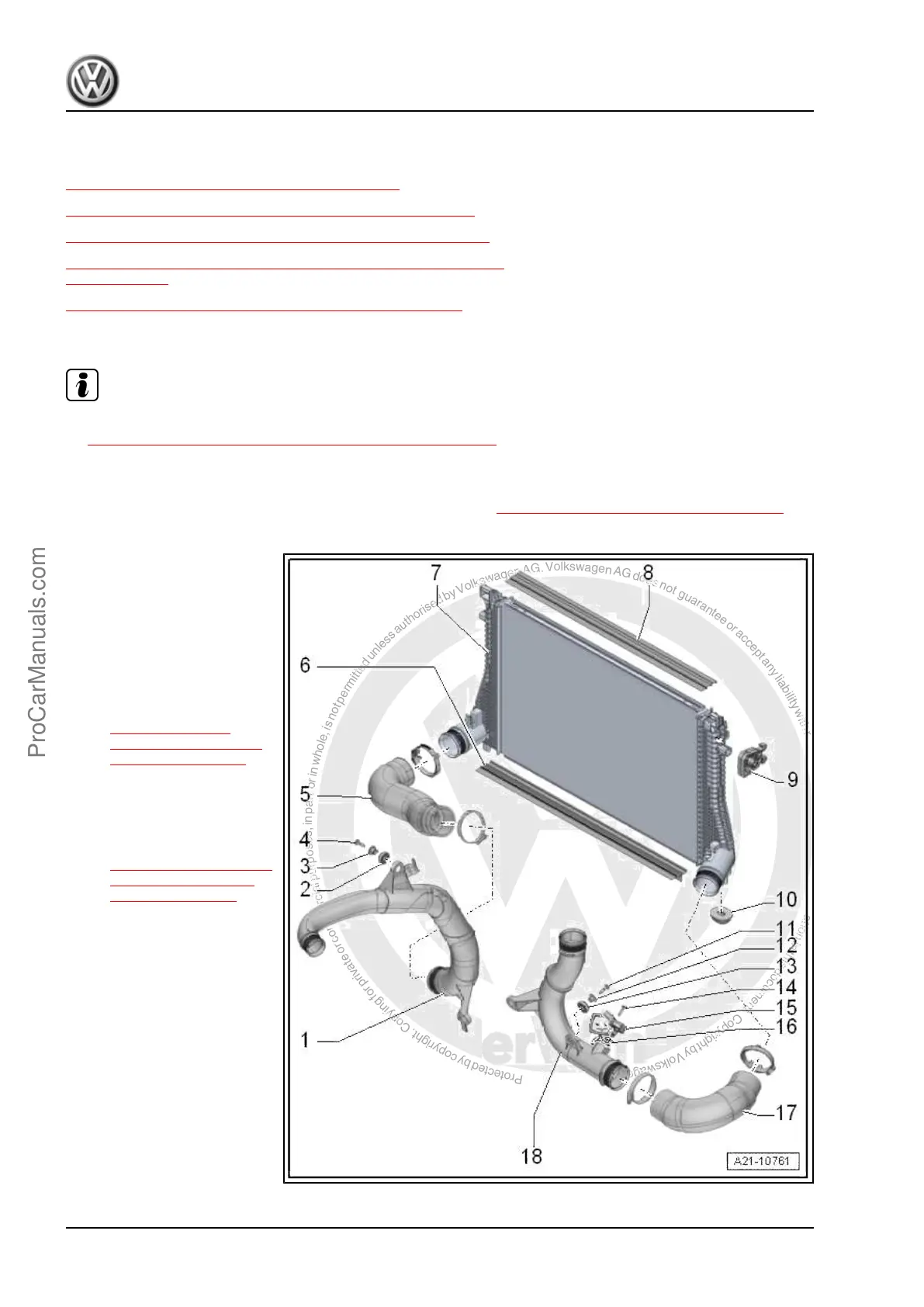
2.1 Overview - Charge Air System
Note
♦
Assembly of screw-type clamps for the charge air hose connections. Refer to
⇒ 2.2 Overview - Charge Air Hose Connections, page 265 .
♦
Before testing or performing a repair, check all air guide pipes and hoses and all vacuum lines for leaks and
secure seating.
♦
Follow the guidelines for clean working conditions. Refer to ⇒ 3.1 Clean Working Conditions, page 5 .
1 - Air Guide Pipe
2 - Grommet
3 - Spacer Sleeve
4 - Bolt
❑ 7 Nm
5 - Air Guide Hose
❑ Installing. Refer to
⇒ 2.2 Overview -
Charge Air Hose Con‐
nections, page 265 .
6 - Air Guide
7 - Charge Air Cooler
❑ Removing and instal‐
ling. Refer to
⇒ 2.3 Charge Air Cool‐
er, Removing and In‐
stalling, page 265 .
8 - Air Guide
9 - Rubber Bushing
❑ For the charge air cooler
10 - Rubber Bushing
❑ For the charge air cooler
11 - Bolt
❑ 7 Nm
12 - Spacer Sleeve
13 - Grommet
14 - Bolt
❑ 5 Nm
Golf 2015 ➤ , Golf Variant 2015 ➤
Engine Mechanical, Fuel Injection and Ignition - Edition 04.2015
264 Rep. Gr.21 - Turbocharger, Supercharger
ProCarManuals.com
 Loading...