P
r
o
t
e
c
t
e
d
b
y
c
o
p
y
r
i
g
h
t
.
C
o
p
y
i
n
g
f
o
r
p
r
i
v
a
t
e
o
r
c
o
m
m
e
r
c
i
a
l
p
u
r
p
o
s
e
s
,
i
n
p
a
r
t
o
r
i
n
w
h
o
l
e
,
i
s
n
o
t
p
e
r
m
i
t
t
e
d
u
n
l
e
s
s
a
u
t
h
o
r
i
s
e
d
b
y
V
o
l
k
s
w
a
g
e
n
A
G
.
V
o
l
k
s
w
a
g
e
n
A
G
d
o
e
s
n
o
t
g
u
a
r
a
n
t
e
e
o
r
a
c
c
e
p
t
a
n
y
l
i
a
b
i
l
i
t
y
w
i
t
h
r
e
s
p
e
c
t
t
o
t
h
e
c
o
r
r
e
c
t
n
e
s
s
o
f
i
n
f
o
r
m
a
t
i
o
n
i
n
t
h
i
s
d
o
c
u
m
e
n
t
.
C
o
p
y
r
i
g
h
t
b
y
V
o
l
k
s
w
a
g
e
n
A
G
.
2 Cylinder Block, Transmission Side
⇒ 2.1 Overview - Cylinder Block, Transmission Side,
page 57
⇒ 2.2 Flywheel, Removing and Installing, page 58
⇒ 2.3 Sealing Flange, Removing and Installing, Transmission
Side, page 59
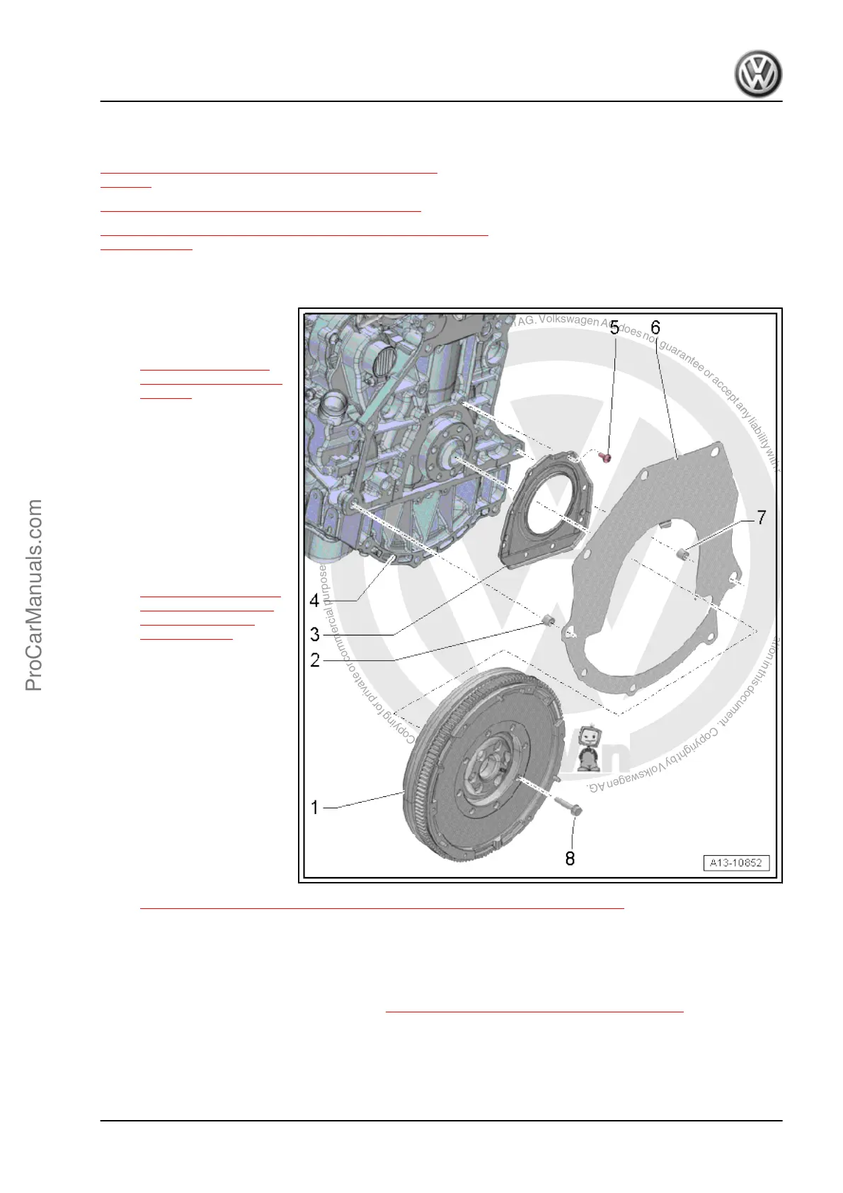
2.1 Overview - Cylinder Block, Transmission Side
1 - Flywheel
❑ Removing and instal‐
ling. Refer to
⇒ 2.2 Flywheel, Re‐
moving and Installing,
page 58 .
❑ It is possible to install in
one position only, the
holes are offset.
2 - Alignment Sleeve
3 - Sealing Flange, Transmis‐
sion Side
❑ With seal
❑ Replace after removing
❑ Removing and instal‐
ling. Refer to
⇒ 2.3 Sealing Flange,
Removing and Instal‐
ling, Transmission
Side, page 59 .
❑ Do not oil or grease the
sealing lip of seal
❑ Wipe off any oil on the
crankshaft bearing pin
with a clean cloth before
installing.
❑ Guide sleeve may only
be removed after the
sealing flange has been
slid onto the crankshaft
pin.
4 - Cylinder Block
5 - Bolt
❑ Tightening specification
and sequence. Refer to
⇒ 2.3 Sealing Flange, Removing and Installing, Transmission Side, page 59 .
6 - Intermediate Plate
❑ Illustration does not correspond to version in vehicle.
❑ Must be located on dowel sleeves
❑ Be careful not to damage or bend when installing
❑ Is hooked in at sealing flange. Refer to ⇒ Fig. Installing Intermediate Plate , page 58
7 - Alignment Sleeve
8 - Bolt
❑ 60 Nm + 90° turn
❑ Replace after removing
Golf 2015 ➤ , Golf Variant 2015 ➤
Engine Mechanical, Fuel Injection and Ignition - Edition 04.2015
2. Cylinder Block, Transmission Side 57
ProCarManuals.com
 Loading...