P
r
o
t
e
c
t
e
d
b
y
c
o
p
y
r
i
g
h
t
.
C
o
p
y
i
n
g
f
o
r
p
r
i
v
a
t
e
o
r
c
o
m
m
e
r
c
i
a
l
p
u
r
p
o
s
e
s
,
i
n
p
a
r
t
o
r
i
n
w
h
o
l
e
,
i
s
n
o
t
p
e
r
m
i
t
t
e
d
u
n
l
e
s
s
a
u
t
h
o
r
i
s
e
d
b
y
V
o
l
k
s
w
a
g
e
n
A
G
.
V
o
l
k
s
w
a
g
e
n
A
G
d
o
e
s
n
o
t
g
u
a
r
a
n
t
e
e
o
r
a
c
c
e
p
t
a
n
y
l
i
a
b
i
l
i
t
y
w
i
t
h
r
e
s
p
e
c
t
t
o
t
h
e
c
o
r
r
e
c
t
n
e
s
s
o
f
i
n
f
o
r
m
a
t
i
o
n
i
n
t
h
i
s
d
o
c
u
m
e
n
t
.
C
o
p
y
r
i
g
h
t
b
y
V
o
l
k
s
w
a
g
e
n
A
G
.
– Using a Cylinder Dial Bore Gauge - VAS6078- measure in a
diagonal sequence at three positions transversely -A- and lon‐
gitudinally -B-.
♦ Deviation from specified size: maximum 0.08 mm
Basic Dimension Cylinder Bore Diame‐
ter
in mm 82.51
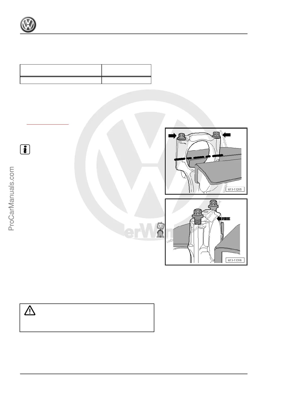
5.4 New Connecting Rod, Separating
New connecting rods might not be separated at the location
where they should be. If the connecting rod bearing cap cannot
be removed by hand, proceed as follows:
– Label which cylinder goes with the connecting rod -item 11-
⇒ Item 11 (page 78) .
– Lightly clamp the connecting rod in a vise equipped with alu‐
minum protective pads.
Note
♦
Clamp the connecting rod lightly to prevent damaging it.
♦
Clamp the connecting rod below the dotted line.
– Loosen the bolts -arrows- approximately 5 turns.
– Carefully tap against the connecting rod bearing cap in direc‐
tion of -arrow- with a plastic hammer until the cap is loose.
5.5 Connecting Rods, Checking Radial
Clearance
Special tools and workshop equipment required
♦
Plastigage
®
Caution
This procedure contains mandatory replaceable parts. Refer
to component overview prior to starting procedure.
Mandatory Replacement Parts
♦ Bolts - Connecting Rod
Procedure
– Remove the connecting rod bearing cap.
Golf 2015 ➤ , Golf Variant 2015 ➤
Engine Mechanical, Fuel Injection and Ignition - Edition 04.2015
84 Rep. Gr.13 - Crankshaft, Cylinder Block
ProCarManuals.com
 Loading...