P
r
o
t
e
c
t
e
d
b
y
c
o
p
y
r
i
g
h
t
.
C
o
p
y
i
n
g
f
o
r
p
r
i
v
a
t
e
o
r
c
o
m
m
e
r
c
i
a
l
p
u
r
p
o
s
e
s
,
i
n
p
a
r
t
o
r
i
n
w
h
o
l
e
,
i
s
n
o
t
p
e
r
m
i
t
t
e
d
u
n
l
e
s
s
a
u
t
h
o
r
i
s
e
d
b
y
V
o
l
k
s
w
a
g
e
n
A
G
.
V
o
l
k
s
w
a
g
e
n
A
G
d
o
e
s
n
o
t
g
u
a
r
a
n
t
e
e
o
r
a
c
c
e
p
t
a
n
y
l
i
a
b
i
l
i
t
y
w
i
t
h
r
e
s
p
e
c
t
t
o
t
h
e
c
o
r
r
e
c
t
n
e
s
s
o
f
i
n
f
o
r
m
a
t
i
o
n
i
n
t
h
i
s
d
o
c
u
m
e
n
t
.
C
o
p
y
r
i
g
h
t
b
y
V
o
l
k
s
w
a
g
e
n
A
G
.
❑ Tightening specification and sequence. Refer to
⇒ 2.4 Pendulum Support, Removing and Installing, page 33 .
10 - Bolt
❑ Replace after removing
❑ Tightening specification and sequence. Refer to
⇒ 2.4 Pendulum Support, Removing and Installing, page 33 .
11 - Bolt
❑ Replace after removing
❑ Tightening specification and sequence. Refer to
⇒ 2.4 Pendulum Support, Removing and Installing, page 33 .
12 - Bolt
❑ 60 Nm + 90° turn
❑ Replace after removing
13 - Bolt
❑ 60 Nm + 90° turn
❑ Replace after removing
14 - Transmission Mount
❑ With support arm
❑ Removing and installing. Refer to ⇒ 2.3 Transmission Mount, Removing and Installing, page 31 .
15 - Bolt
❑ 50 Nm + 90° turn
❑ Replace after removing
2.2 Engine Mount, Removing and Installing
Caution
This procedure contains mandatory replaceable parts. Refer
to component overview prior to starting procedure.
Mandatory Replacement Parts
♦ Bolts - Engine Mount
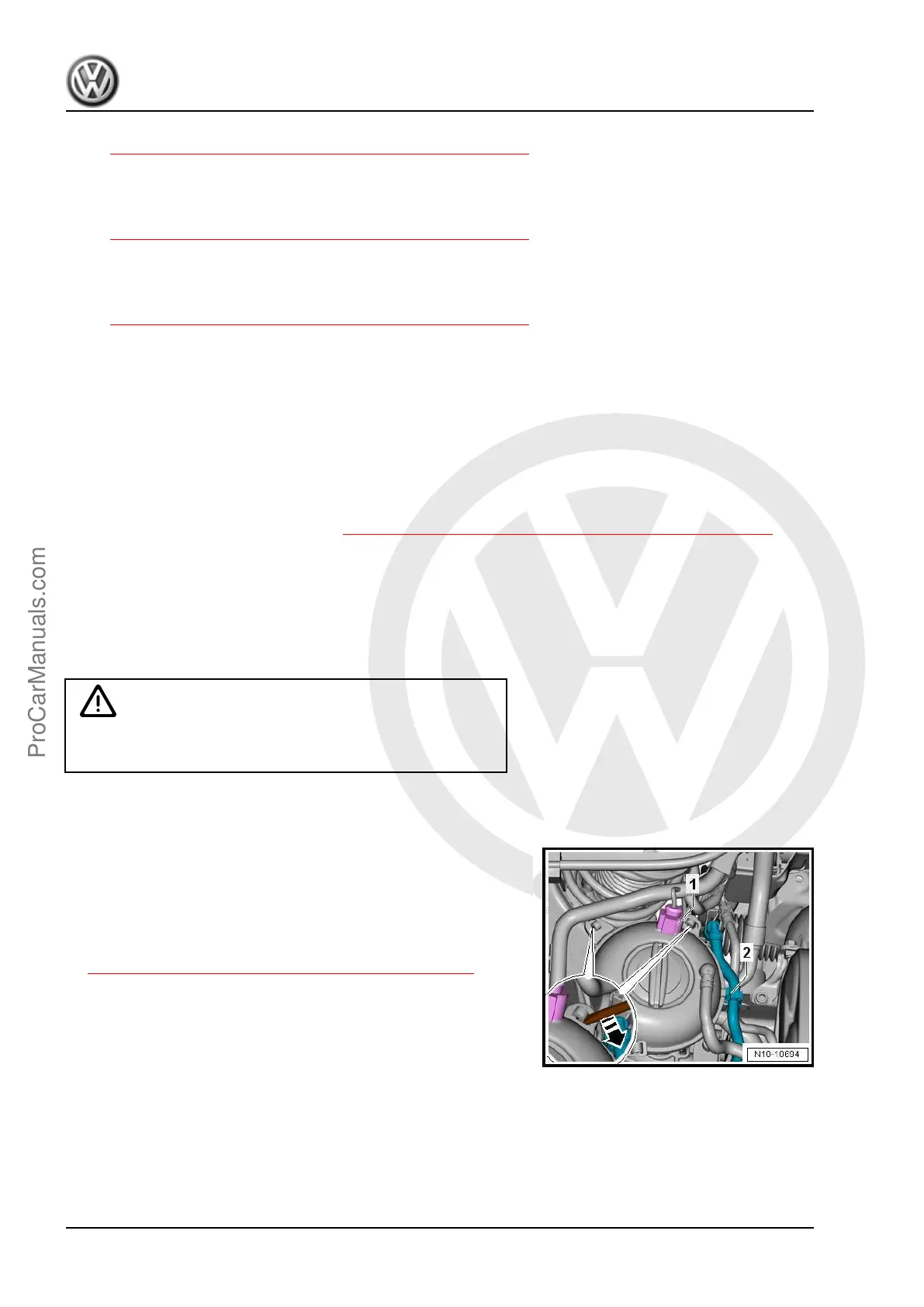
– Disconnect the connector -1-.
– Free up the hoses -2-.
– Release the retainers with a screwdriver in direction of
-arrow- and move the coolant expansion tank to the side.
– Support the engine in its installed position. Refer to
⇒ 2.5 Engine, Supporting in Installed Position, page 33 .
– Slightly pretension the engine/transmission assembly with the
spindle, do not lift.
Golf 2015 ➤ , Golf Variant 2015 ➤
Engine Mechanical, Fuel Injection and Ignition - Edition 04.2015
30 Rep. Gr.10 - Engine Assembly
ProCarManuals.com
 Loading...