HARDWARE S ETUP
VF8 DELTA/DELTA XL/KAPPA 23-11
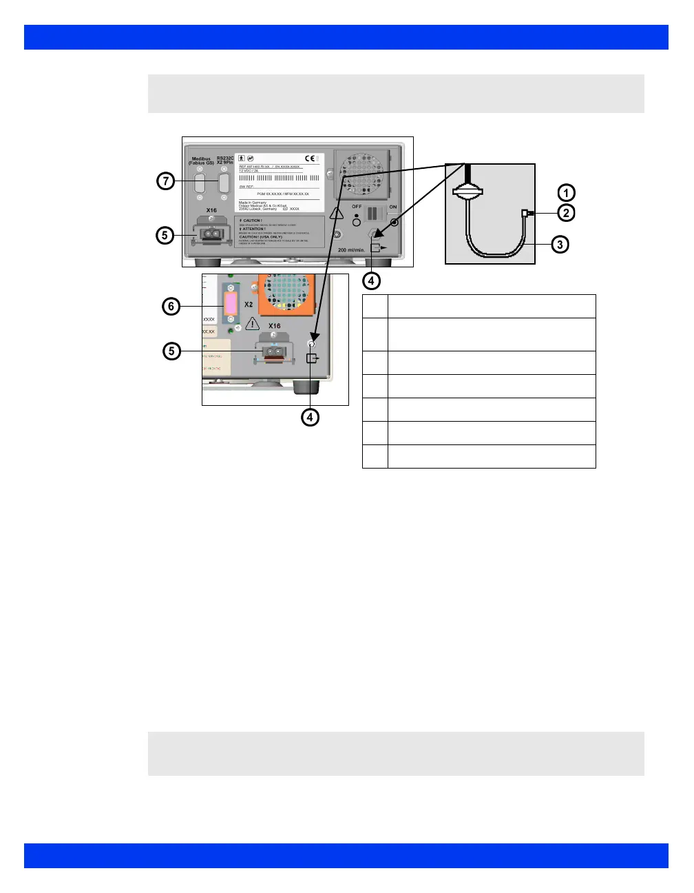
4. Connect one end of the Scio connecting cable to the X2 connector at the rear
of the module and the other end to the Delta/Delta XL/Kappa monitor or to
the IDS (see “Cable Connections” on page 23-9). If you are using a breakout
box, connect the end to the connector on the breakout box.
5. Connect the power supply to the external power supply connector at the rear
of the module.
6. Connect the power supply cord to a hospital outlet.
Warm-Up
Upon start-up, the Scio module passes through an initialization and warm-up period.
During this time, the etCO
2
* (in some models O
2
) and/or agent parameter boxes
display a question mark.
NOTE: The exhaust port is a hose barb type connector.
CAUTION: During warm-up, reported values might not be accurate. To achieve full
accuracy, a typical warm-up period of 7 minutes is recommended.
1
Bacterial filter
2
To sample gas recirculation sys-
tem (or gas scavenging system)
3
Sample gas return tubing
4
Exhaust port
5
External power supply connector
6
X2 connector
7
RS232C connector (X2 9 pin)
 Loading...