Chapter 3 149
Assembly Replacement
Procedure 1. Spectrum Analyzer Cover
Procedure 1. Spectrum Analyzer Cover
Removal/Replacement
1. Disconnect the line-power cord, remove any adapters from the front
panel connectors, and place the spectrum analyzer on its front panel.
2. If an HP 85620A Mass Memory Module or HP 85629B Test and
Adjustment Module is mounted on the rear panel, remove it. Loosen
(but do not remove) the four rear-bumper screws, using a 4 mm hex
wrench. Pull the cover assembly off towards the rear of the
instrument.
CAUTION When replacing the spectrum analyzer cover, use caution to avoid
damaging any cables.
3. When installing the cover assembly, be sure to locate the cover air
vent holes on the bottom side of the spectrum analyzer. Attach with
the four screws loosened in step 2, and tighten the four screws
gradually to ensure that the cover is seated in the front frame gasket
groove.
4. Torque each screw to 40 to 50 inch-pounds to ensure proper gasket
compression to minimize EMI.
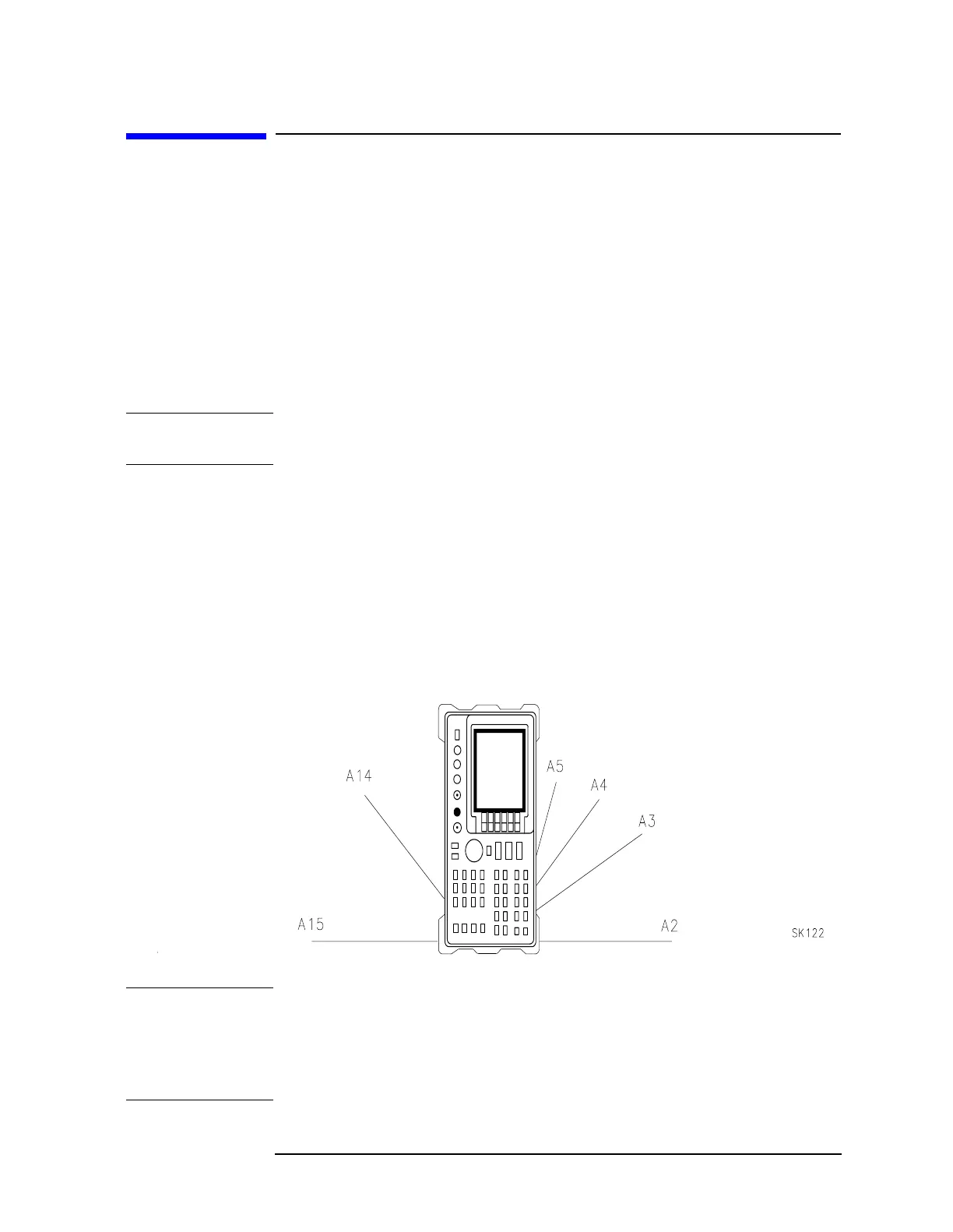
Figure 3-1 Hinged Assemblies
NOTE Figure 3-1 shows an 8560 E-series instrument. In the assembly removal
and replacement procedures the words “left” and “right ” assume you
are facing the front panel of the instrument, as shown in Figure 3-1,
with A14 and A15 to your left, and A2 through A5 on your right. The
8560 EC-series instrument is identical except the A2 board is smaller.

 Loading...


