Chapter 6 333
General Troubleshooting
Block Diagram Description
Control for the amplifiers originates from two DACs on the A3 interface
assembly. (DAC values are interpolated approximately every 17 MHz
based on data obtained during the frequency response adjustment.) A15
flatness-compensation control circuitry converts the RF GAIN voltage,
from A3, into two currents: RF GAIN1 and RF GAIN2. These currents
drive PIN diodes in the flatness compensation amplifiers.
Synthesizer Section
The first LO is phase-locked to the internal 10 MHz standard of the
instrument by four PLLs. See Figure 6-7 on page 335.
The Reference PLL supplies reference frequencies for the instrument.
The three remaining PLLs tune and phase-lock the LO through its
frequency range. To tune the LO to a particular frequency, the
instrument microprocessor must set the programmable feedback
dividers (N) and reference dividers (R) contained in each PLL.
Sweeping the First LO
The spectrum analyzer uses a method called lock and roll to sweep the
first LO (A11 YTO) for LO spans >2 MHz. This involves phase-locking
the spectrum analyzer at the start frequency during the retrace of the
sweep, then sweeping through the desired frequency range in an
unlocked condition. The sweep ramp, which sweeps the LO during the
roll part of the lock and roll process, is generated on the A14 frequency
control assembly. It is applied to either A11 YTO main coil or the A11
YTO FM coil. For LO spans≤2.0 MHz, the YTO PLL remains locked and
the fractional N PLL sweeps while remaining phase locked. The
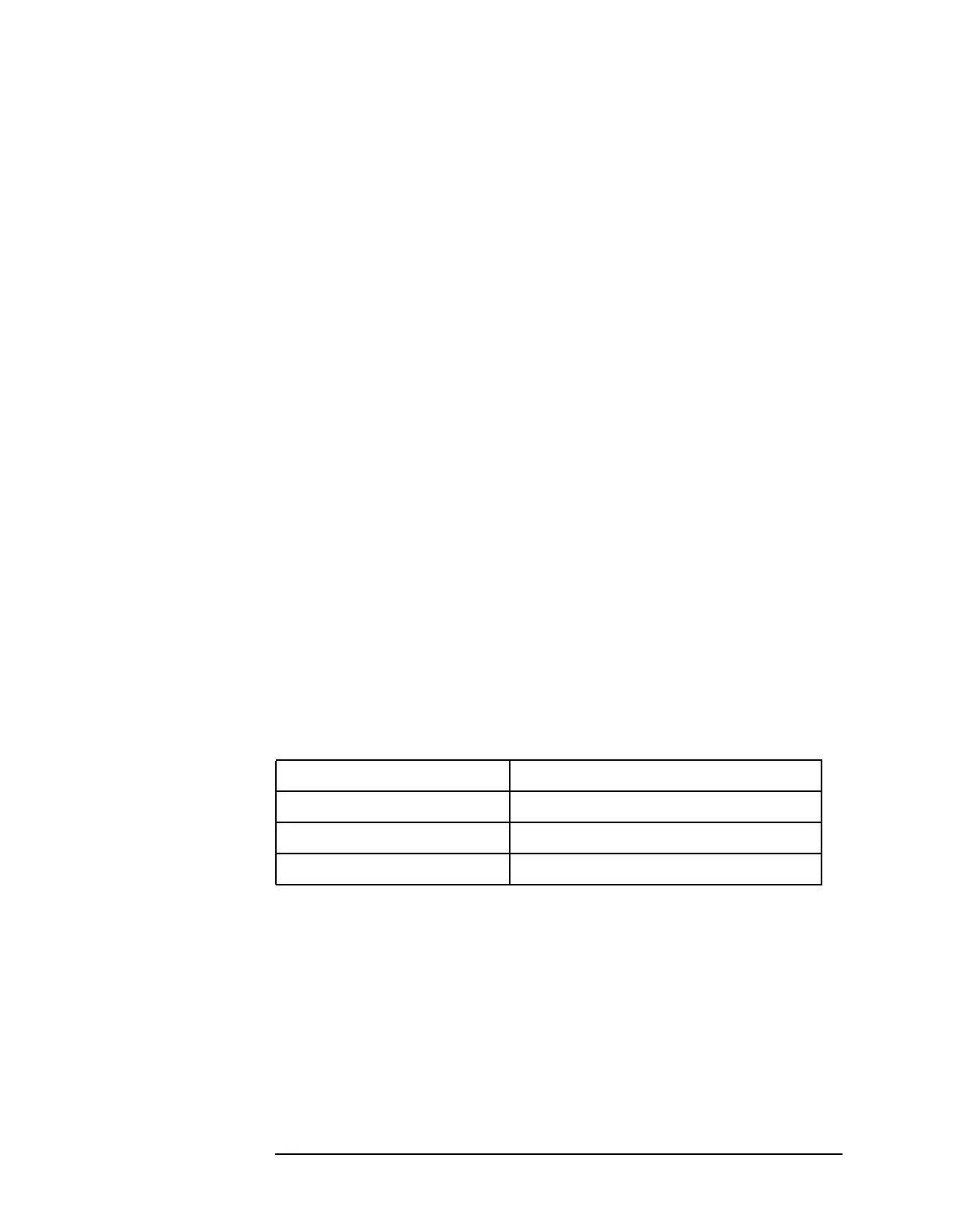
frequency/span relationships are as follows:
When the sweep ramp is applied to the YTO, the spectrum analyzer
must prevent this loop from trying to compensate for changes in the
output frequency. To accomplish this, the spectrum analyzer breaks the
PLL by disconnecting the YTO PLL phase detector output.
Reference PLL (part of A15)
The 600 MHz reference PLL provides 600 MHz for the second LO and
the A10 tracking generator (Option 002), 300 MHz for the third LO, and
the sampling oscillator reference and 10 MHz to the fractional N PLL.
The reference PLL is locked to a 10 MHz OCXO (oven-compensated
Table 6-2 Location of Assembly Troubleshooting Text
A11 YTO Spanwidth Sweep Applied To
20.1 MHz to 3.8107 GHz A11 YTO main coil
2.01 MHz to 20.0 MHz A11 YTO FM coil
100 Hz to 2 MHz Fractional N phase locked loop

 Loading...


