Chapter 10 549
Synthesizer Section
Unlocked Fractional N PLL
A15 RF assembly.
3. Change the spectrum analyzer from the fractional N span to 0 Hz.
4. Check the frequency at A14TP1. It should equal the value found by
pressing
CAL, MORE 1 OF 2, FREQ DIAGNOSE, and RAW OSC FREQ.
5. Check the tune voltage at the ungrounded end of C135.
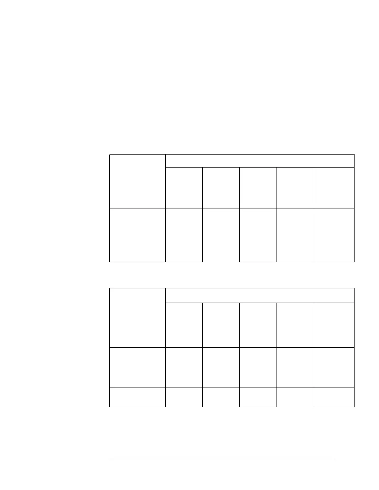
6. Look up the expected problem area in Table 10-12 on page 549 with
the information from steps 4 and 5. Go to the appropriate
troubleshooting steps.
Table 10-12 Unlocked Fractional N Troubleshooting Areas (08560-60069 and
Above)
Measured VCO
Frequency
Relative to
Expected Value
Tune Voltage
Less than
−4 V
About
−3.3 V
Between
−2 V and
+10 V
About
+11 V
Greater
than
+12.5 V
Measured >
expected
VCO clamp VCO Divider or
integrator
Divider or
integrator
VCO clamp
Measured <
expected
VCO clamp Divider or
integrator
Divider or
integrator
VCO VCO clamp
Measured, not
oscillating
VCO clamp VCO VCO VCO VCO clamp
Table 10-13 Unlocked Fractional N Troubleshooting Areas (08560-60062 and
below)
MeasuredVCO
Frequency
Relative to
Expected
Value
Tune Voltage
Less
than
−12.5 V
About
−11 V
Between
±10 V
About
+11 V
Greater
than+12.5
V
Measured >
expected
VCO
clamp
VCO Divideror
integrator
Divideror
integrator
VCO clamp
Measured <
expected
VCO
clamp
Divideror
integrator
Divideror
integrator
VCO VCO clamp
Measured, not
oscillating
VCO
clamp
VCO VCO VCO VCO clamp

 Loading...


