Chapter 12 621
Display/Power Supply Section
Troubleshooting the LCD Display
Troubleshooting the LCD Display
NOTE There are no adjustments for intensity or contrast of the LCD.
Blank Display
1. If the LED above the front-panel LINE switch is lit, most of the A6
power supply is functioning properly.
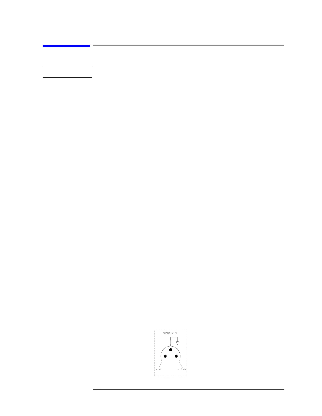
2. Carefully check the voltages on the front-panel PROBE POWER
jack. Be careful to avoid shorting the pins together. See Figure 12-2
on page 621.
3. Check that the fan is operating. If the PROBE POWER voltages are
correct, and the fan is turning, the A6 power supply is probably
working properly.
4. If all of the power supply indicators along the outside edge of the A2
controller assembly are lit, the A6 power supply is probably working
properly.
5. Connect a VGA monitor to the VGA port on the rear of the
instrument. If the display is still blank, suspect the A2 controller, a
loose cable, or the display driver.
6. If the LED is not lit, or the fan is not working, or the probe power
voltages are not correct, or the power supply indicators on the edge
of the A2 controller assembly are not working properly, proceed to
the section on troubleshooting the power supply on page 642.
7. Open the left side of the instrument (see procedure A2 on page
150). Make voltage measurements at pins 1, 2, 3, 4, 5, 41, 42, 43, 44,
and 45 on J8 of the A2 controller (see Figure 12-3 on page 623).
These pins should measure 5V±0.25V. If any of these measurements
is out of tolerance suspect the A2 controller board or the power
supply. If the voltages for these pins are correct, make the same
measurements at the identical pins on J1 of the A17 display driver
board. If these measurements are correct, suspect the A18 LCD
assembly or the A17A1 inverter board. If these measurements are
not correct, suspect the A17 LCD driver or A17A1 inverter board.
Figure 12-2 Probe Power Socket

 Loading...


