558 Chapter10
Synthesizer Section
Frequency Span Accuracy Problems
7. Set the HP 8560E/EC to the following settings:
Center frequency ..................................................... 300MHz
Span .................................................................................0Hz
Trigger ............................................................ SINGLE,EXT
a. On the HP 8560E/EC, press
SAVE, SAVE STATE, STATE 0.
b. Remove jumper A14J23 and connect a dc voltage source to
A14J23 pin 2. Connect the voltage source ground to A14J23 pin 3.
c. Connect a microwave frequency counter or spectrum analyzer to
the HP 8560E/EC 1ST LO OUTPUT (front panel output).
d. Set the dc voltage source output for 0 Vdc and note the 1st LO
frequency.
e. Set the dc voltage source output for +10 Vdc. The first LO
frequency should momentarily increase approximately
+15.6 MHz.
f. The voltage at A14U332 pin 2 should be approximately 19% of
the voltage at A14J23 pin 2.
g. If the first LO frequency did not change in step e, turn off the HP
8560E/EC
LINE switch and disconnect W10 from A14J3.
h. Place a jumper between A14J3 pins 9 and 10. Place a 50 Ω,3watt
resistor across A14J3 pins 5 and 6 (resistor, HP part number
0811-1086). Set the
LINE switch on.
i. On the HP 8560E/EC, press
RECALL, STATE, STATE 0.
j. The voltage at A14U332 pin 2 should be approximately 19% of
the voltage at A14J23 pin 2.
k. If the voltage at U332 pin 2 is correct with A14J3 pins 9 and 10
shorted, but was incorrect with W10 connected, the YTO FM coil
is probably open; replace the A11 YTO.
l. Replace jumper A14J23. Remove the jumper and resistor from
A14J3. Reconnect W10 to A14J3.
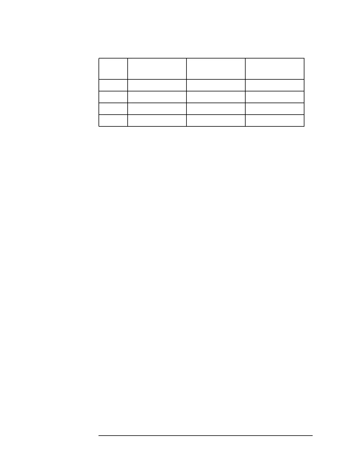
Table 10-17 Settings of Sweep Switches
Switch Switch State Switch Control
Line (Pin #)
Control Line
State (TTL)
U318A Closed 1 High
U318B Open 16 High
U318C Closed 9 Low
U318D Open 8 Low

 Loading...


