Chapter 3 163
Assembly Replacement
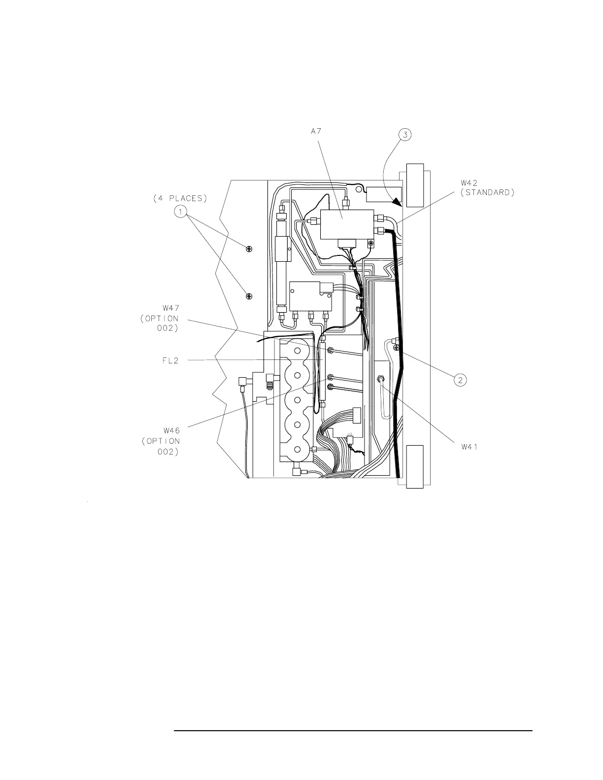
Procedure 2B. A1 Front Frame/A18 CRT (8560E)
Figure 3-4 A9, A18, and Line Switch Assembly Mounting Screws
17.Remove screw (2) securing the A9 input attenuator assembly to the
center support on the front frame. See Figure 3-4 on page 163.
18.Use a 5/16-inch open-end wrench to disconnect W41 from the front
panel INPUT 50 Ω connector. Loosen the opposite end of W41.
19.For Option 002 spectrum analyzers: use a 5/16-inch open-end wrench
to disconnect W47 from the front panel RF OUT 50 Ω connector.
20.Disconnect W42 from A7J3 and the front panel 1ST LO OUTPUT
connector. For Option 002 spectrum analyzers: disconnect W46 from
the front panel 1ST LO OUTPUT connector.
21.Disconnect W36, coax 86, from the front panel IF INPUT connector.

 Loading...


