Chapter 10 535
Synthesizer Section
Unlocked Offset Lock Loop (Sampling Oscillator)
oscillator is 296 MHz.
6. The voltage required to tune the oscillator should measure between
+15 Vdc and +19 Vdc. If the voltage is out of this range, perform the
sampling oscillator adjustment in Chapter 2.
7. Vary the voltage to tune the sampling oscillator to 296 MHz.
8. Use an active probe/spectrum analyzer combination to measure the
300 MHz LO signal at the following test point:
9. If the signal is not measured near the indicated power, troubleshoot
the offset lock loop buffer (function block AM of A15 RF schematic
sheet 3 of 4).
A15TP402 +7 dBm
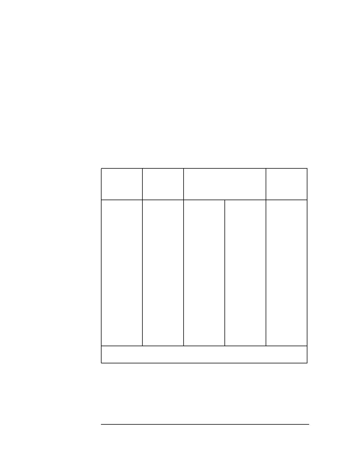
Table 10-7 Sampling Oscillator PLL Divide Numbers
Sampling
Oscillator
Frequency
(MHz)
Center
Frequency*
(MHz)
Reference Divide Chain Reference
Frequency
(MHz)
Prescaler Postscaler
285.000 2156.3 10 2 15.000
286.364 2176.3 11 2 13.636
287.500 2199.5 8 3 12.500
288.462 2230.3 13 2 11.538
288.888 799.3 9 3 11.111
290.000 2263.3 10 3 10.000
290.909 2282.3 11 3 9.091
291.666 2302.3 9 4 8.333
292.500 2155.3 8 5 7.500
293.478 2158.3 23 2 6.522
294.444 2336.3 9 6 5.556
295.000 2196.3 10 6 5.000
296.000 1.3 15 5 4.000
296.471 2378.3 17 5 3.529
297.000 2410.3 20 5 3.000
297.222 2422.3 18 6 2.778
* To set the sampling oscillator to a desired frequency, set span
to 0 Hz and CENTER FREQ to the value listed in the table.

 Loading...


