Chapter 9 477
Controller Section
Display Problems (8560E)
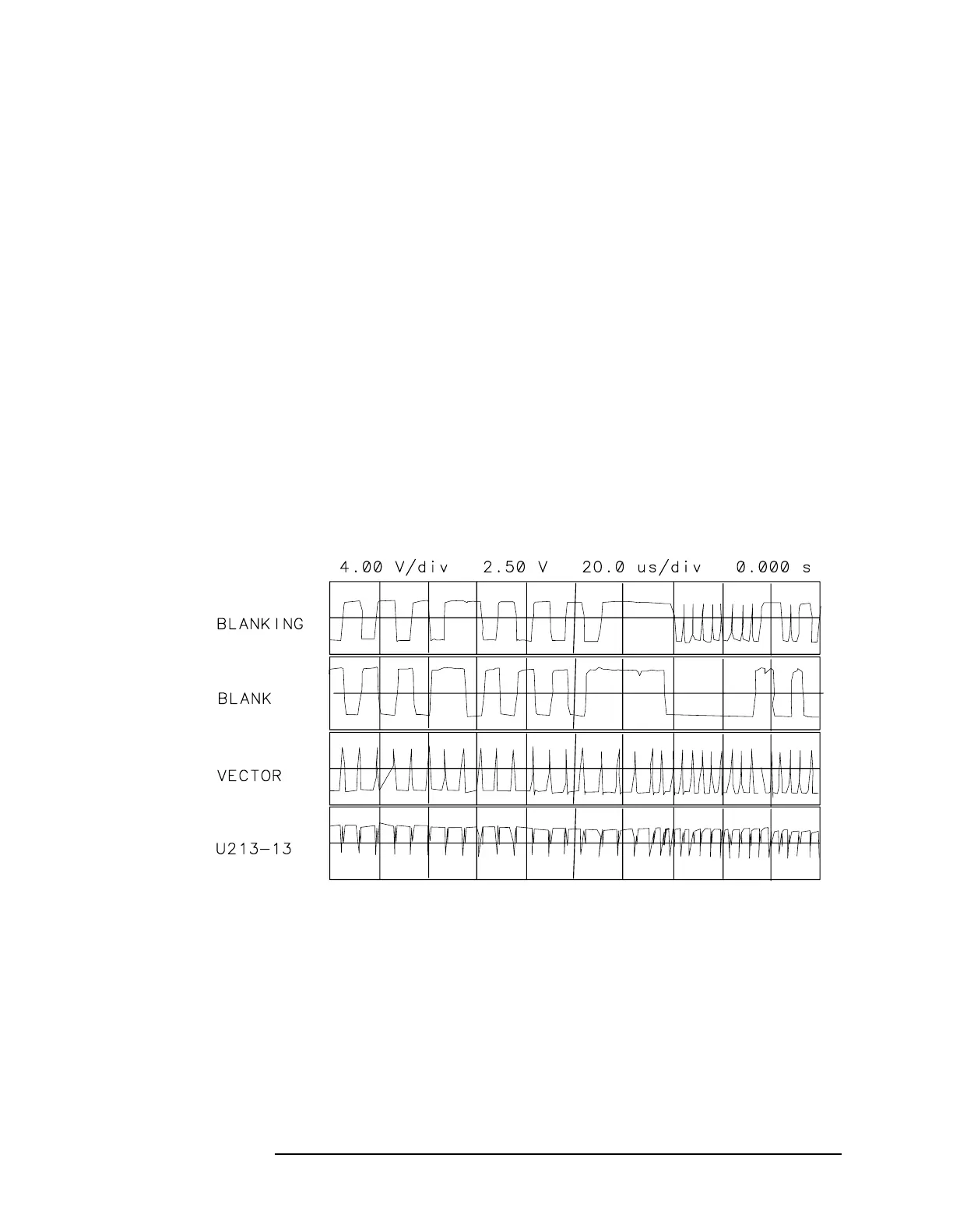
5. The waveforms in Figure 9-3 on page 477 must match the timing of
the vectors being drawn. To do this, U215B is used to adjust the
leading edge, and U215A is used to adjust the trailing edge. The first
six horizontal divisions show the line drawing mode where the
VECTOR pulses are 6 µs apart. The remaining divisions shows
character mode (VECTOR pulses 3 µs apart). The BLANK pulses are
synchronized to the VECTOR pulses by U214B. The fourth trace
shows the double pulses which delay the leading and trailing edges
of the blanking pulses.
6. Set the oscilloscope to the following settings to expand the first and
fourth traces. This displays how the rising edges of U213-13
determine the transitions of the blanking pulses. See Figure 9-4 on
page 478.
Amplitude scale .............................................................4V/div
Amplitude offset .............................................................+2.5V
Sweep time .................................................................. 2µs/div
Delay from trigger ............................................................96µs
Triggering ...................................................................External
Figure 9-3 Blanking Waveforms

 Loading...


