180 Chapter3
Assembly Replacement
Procedure 6A. A6 Power Supply Assembly (8560EC)
Replacement
1. Ensure that the bottom shield wall is in place before replacing the
A6 power supply assembly.
2. Attach the A6 power supply assembly to the spectrum analyzer
chassis and top shield wall using the four screws, torqued to 10-inch
lbs. Attatch all other screws, torqued to 6-inch lbs.
3. Connect W1 to A6J1, W3 to A6J2, fan power wires to A6J3, W8 to
A6J4, and the line-power jack to A6J101. See Figure 3-17 on page
183.
4. Ensure that all cables are safely routed and will not be damaged
when securing the A6 cover.
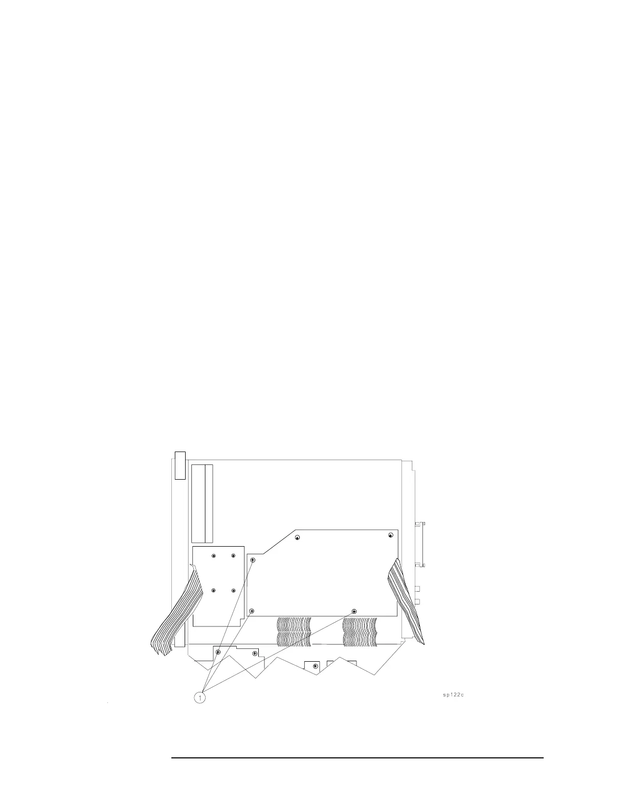
5. Secure the power supply cover shield to the power supply using
three flathead screws (1). See Figure 3-16 on page 180. One end of
the cover fits into a slot provided in the rear frame assembly. Ensure
that the extended portion of the cover shield is seated in the shield
wall groove.
6. Fold the A2, A3, A4, and A5 assemblies into the spectrum analyzer
as described in steps 6 through 12 under "Procedure 5. A2, A3, A4,
and A5 Assemblies Replacement."
Figure 3-16 Power Supply Cover

 Loading...


