476 Chapter9
Controller Section
Display Problems (8560E)
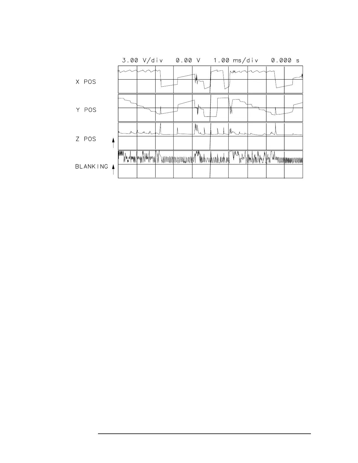
Figure 9-2 Line Generator Output Waveforms
Blanking
Refer to function block J of A2 Controller Schematic Diagram (sheet 1
of 4) in the HP 8560 E-Series Component Level Information.
1. Using an oscilloscope, check for blanking pulses at A2J202 pin 15.
A2U206 pin 6 should be at a TTL high. Blanking pulses turn the
CRT beam off during the sample time of the line generators and
when moving the CRT beam to a new position for drawing the next
vector.
2. Set an oscilloscope to the following settings:
Amplitude scale ........................................................... 4V/div
Amplitude offset ........................................................... +2.5V
Sweep time .............................................................. 20µs/div
Triggering .................................................................External
3. Externally trigger the oscilloscope off the signal at A2U207 pin 8
(LBRIGHT).
4. Compare the blanking-circuit input signals at the following test
points with those illustrated in Figure 9-3 on page 477.
BLANKING: J202 pin 15
BLANK: U214 pin 12
VECTOR: U214 pin 11
U213 pin 13

 Loading...