194 Chapter3
Assembly Replacement
Procedure 8. A7 through A13 Assemblies
A10 Tracking Generator (Option 002)
Removal
1. Use a 5/16-inch wrench to remove the A10 tracking generator RF
OUT, LO OUT, and LO IN semi-rigid cables.
2. Disconnect W14 and W16 from the A10 tracking generator.
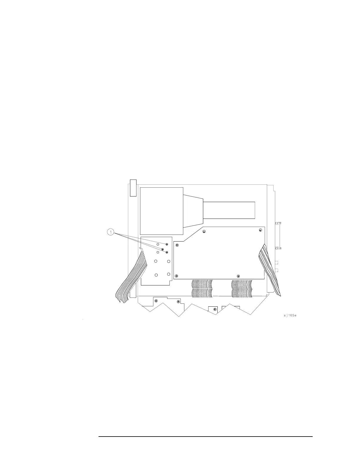
3. Remove the three screws (1) securing the A10 tracking generator to
the center deck. These screws are located on the top side of the
center deck as illustrated in Figure 3-23 on page 194.
4. Remove the A10 tracking generator and disconnect W48, coax 80.
Figure 3-23 A10 Tracking Generator Mounting Screws
Replacement
1. Connect W48, coax 80, to the A10 tracking generator INPUT
connector.
2. Orient the tracking generator so that its LO IN, LO OUT, and RF
OUT connectors are closest to the A13 Second Converter.
3. Loosely connect the LO IN, LO OUT, and RF OUT semi-rigid cables.
4. Secure the A10 tracking generator to the spectrum analyzer center

 Loading...


