Chapter 12 643
Display/Power Supply Section
A6 Power Supply Assembly
the cathode of A6CR201 (TP206) and the ground to A6TP201.
15.Set the current limit of the power supply to about 500 mA and the
voltage to 12 Vdc.
16.Make sure a jumper is connected from A6TP101 to A6TP301. This
independently powers the buck regulator control circuitry.
17.Connect a jumper from the output of a +12 Vdc power supply to the
end of A6R202 physically nearest A6C211.
18.Connect a jumper from +12 Vdc to the end of C207 nearest C209.
19.If the current draw exceeds approximately 50 mA, suspect a short in
the buck regulator control circuitry or a shorted CR201.
20.Check TP204 for an 80 kHz sawtooth (4 Vp-p).
21.Check TP203 and TP207 for 40 kHz square (12 Vp-p). If the
waveforms at either TP203 or TP207 are bad, one of the FETs in the
DC-DC Converter is probably defective.
22.Check TP105 and TP106 for a 12 Vp-p sawtooth waveform that is
flattened at the bottom. If the waveform is a squarewave, the FET to
which the test point is connected has failed or shorted.
23.Check TP202 for 80 kHz pulses (12 Vp-p).
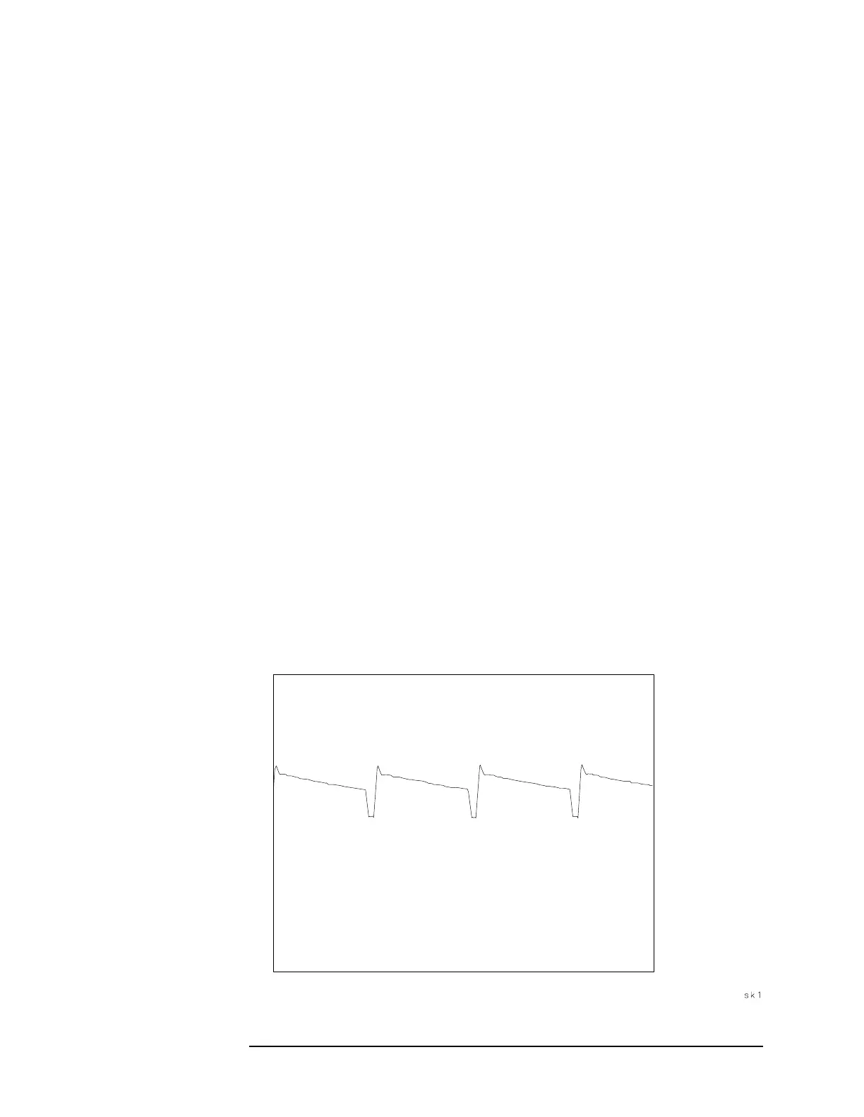
24.Short TP401 to TP102. Check TP103 for a waveform similar to that
in Figure 12-8 on page 643.
25.If the waveform at TP202 is correct but the waveform at TP103 is
bad, suspect either Q102 or CR106.
Figure 12-8 Buck Regulator Waveform

 Loading...


