Chapter 3 165
Assembly Replacement
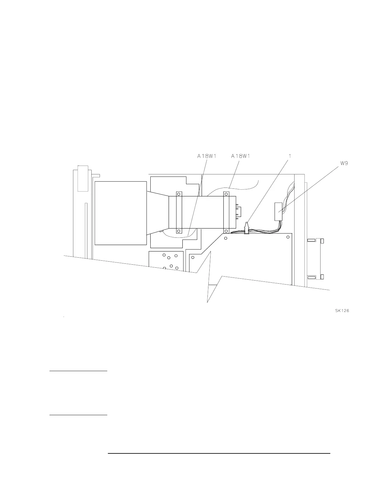
Procedure 2B. A1 Front Frame/A18 CRT (8560E)
30.Pull the cable tie (1) to free W9. See Figure 3-6 on page 165. Gently
pry W9, the CRT cable, from the end of the CRT assembly.
31.Support the A18 CRT assembly while gently pulling the front frame
and CRT out of the spectrum analyzer 1 or 2 inches.
32.Disconnect A18W1, the trace align wires, from A17J5. Remove the
front frame and CRT assemblies.
33.Gently pull the CRT assembly off of the front frame assembly.
Figure 3-6 Installing the CRT and front Frame Assemblies
Replacement
NOTE Use care when handling the glass CRT EMI shield. The glass may be
cleaned using thin film cleaner (HP part number 8500-2163) and a
lint-free cloth. When installing the glass shield, face the side of the
glass with the silver coated edge towards the inside of the spectrum
analyzer.
1. Place the spectrum analyzer on its right side frame with the front
end extending slightly over the front of the workbench.

 Loading...


