546 Chapter10
Synthesizer Section
Unlocked YTO PLL
45.Verify the voltages listed in Table 10-10 on page 546.
46.Place jumper A14J23 in the NORMAL position.
47.Set the HP 8560E/EC to the following settings:
Center frequency ..................................................... 300MHz
Span .................................................................................0Hz
48.Place jumper A14J23 in the TEST position.
49.Measure the output of the main coil tune DAC (A14J18 pin 3) with a
DVM. Refer to function block E of A14 frequency control schematic.
50.If the HP 8560E/EC center frequency is 300 MHz, the voltage at
A14J18 pin 3 should measure −3.35 V ±0.25 V. The voltage may also
be determined from the following equation:
V = −(First LO Frequency −2.95 GHz) × 2.654 V/GHz
51.The voltage at A14U330 pin 2 should measure −3.4 V ±0.2 Vdc. This
represents a current setting the YTO to approximately 2.95 GHz.
52.Return jumper A14J23 to the NORMAL position.
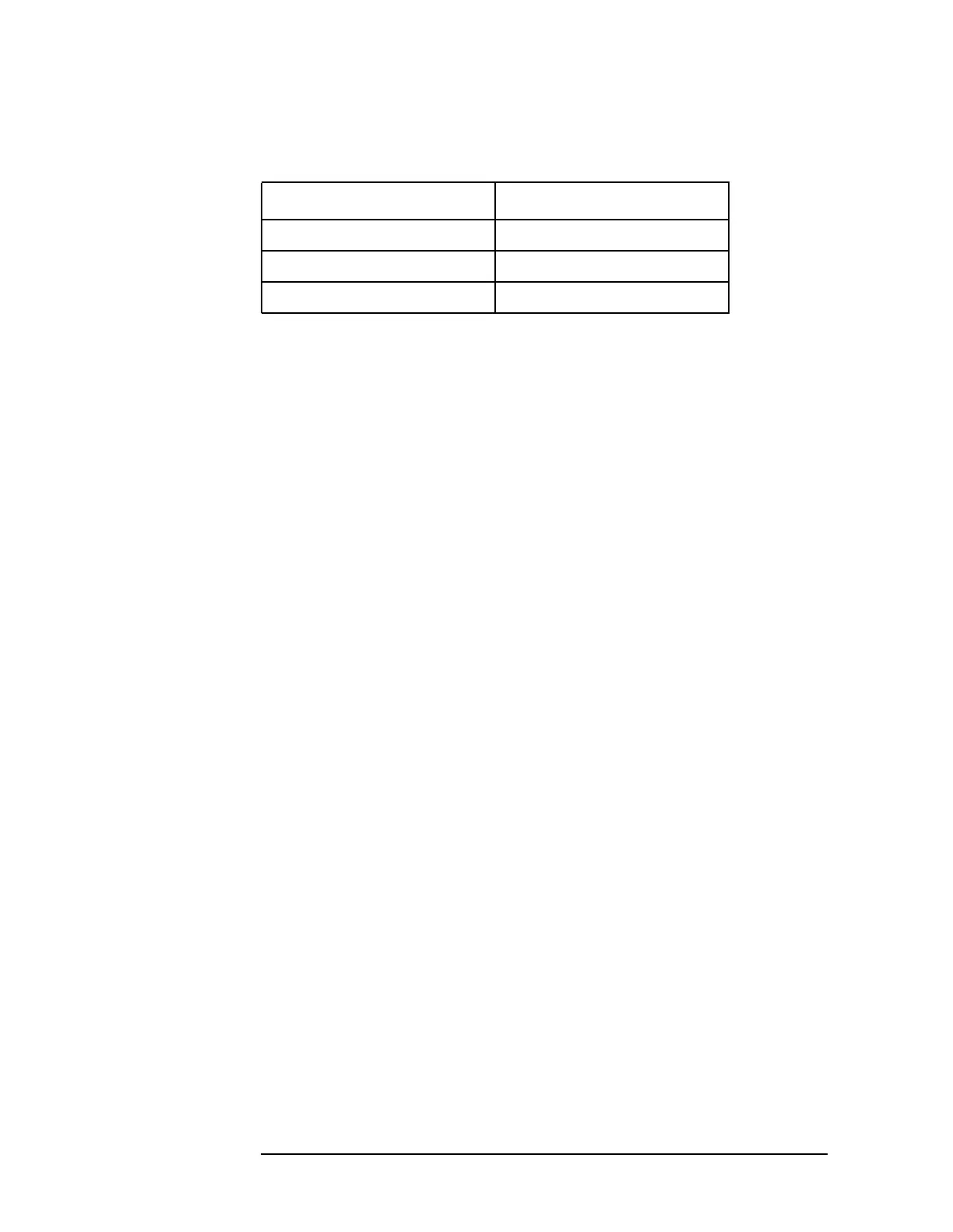
Table 10-10 Main Coil Coarse and Fine DACs Voltages
Measurement Points Voltages
A14J17 pin 2 −5 Vdc
A14J17 pin 3 −5 Vdc
A14J17 pin 5 +5Vdc

 Loading...


