Chapter 7 357
ADC/Interface Section
Troubleshooting Using the TAM
Troubleshooting Using the TAM
When using Automatic Fault Isolation, the TAM indicates suspected
circuits that need to be manually checked. Use Table 7-2 on page 358 to
locate the manual procedure.
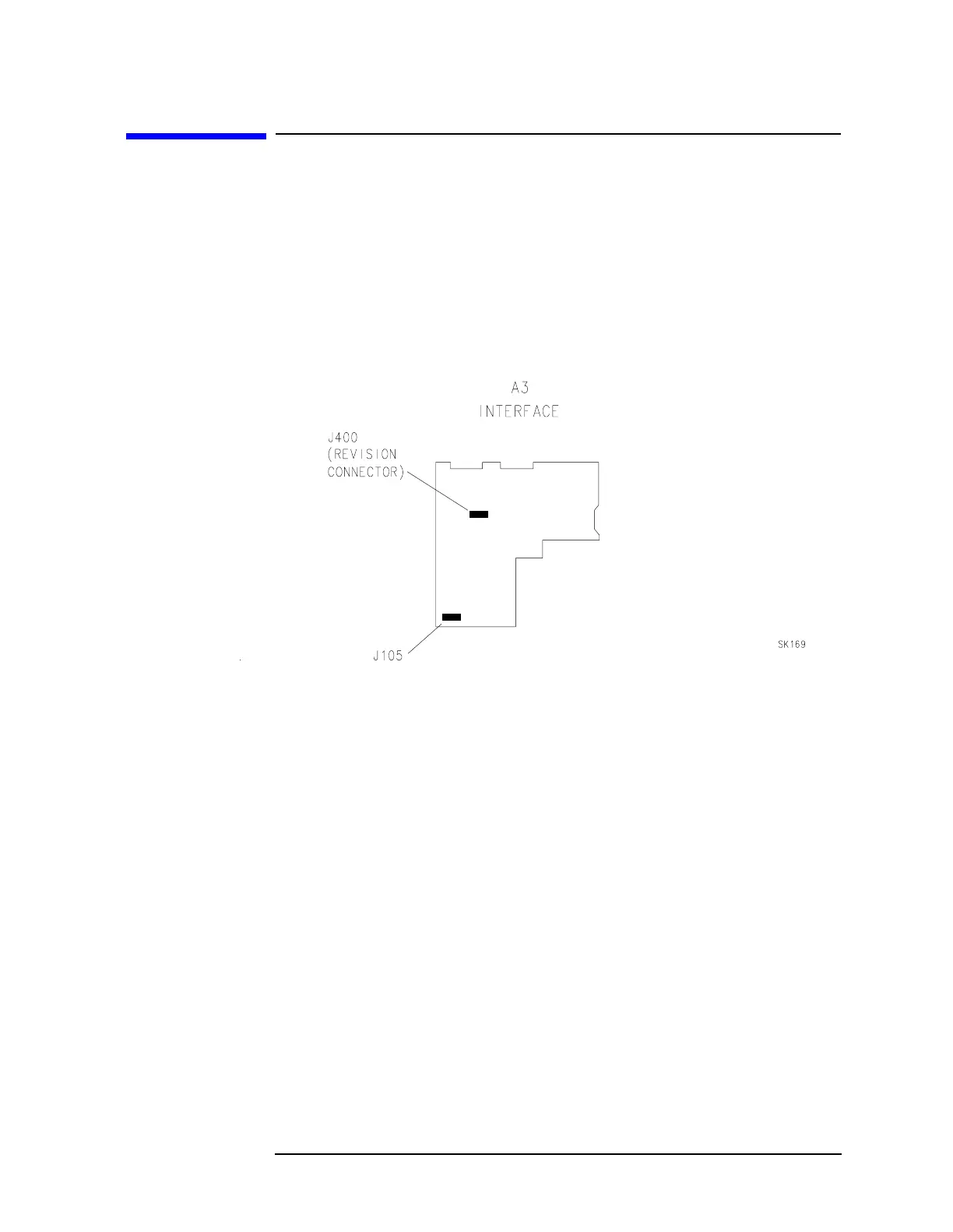
Table 7-3 on page 359 lists assembly test connectors associated with
each Manual Probe Troubleshooting test. Figure 7-1 on page 357
illustrates the location of A3 test connectors.
Figure 7-1 A3 Test Connectors
Automatic Fault Isolation
Analog data bus errors that occur during Automatic Fault Isolation
result from either a shorted W2 control cable or faulty A3 assembly.
Perform the following steps to determine the cause of the error:
1. Disconnect W2 from A3J2 and repeat the Automatic Fault Isolation
procedure.
2. If the analog data bus error is still present, troubleshoot the A3
Interface assembly. If the error disappears, look for a short on W2 or
another assembly connecting to it.
3. To isolate a short on W2, reconnect W2 to A3J2 and disconnect W2
from all other assemblies.
4. Repeat the Automatic Fault Isolation routine.
5. If the analog data bus error is still present, W2 is shorted. If the
error disappears, reconnect the other assemblies one at a time and
repeat the procedure. Once the faulty assembly is reconnected to
W2, the error should reappear.

 Loading...


