164 Chapter3
Assembly Replacement
Procedure 2B. A1 Front Frame/A18 CRT (8560E)
22.Remove the VOLUME knob and potentiometer from the front panel.
If necessary, drill out the nut driver used to remove the VOLUME
potentiometer and cover the tip with heatshrink tubing or tape to
avoid scratching the enameled front panel.
23.Use a 9/16-inch nut driver to remove the dress nut holding the front
panel CAL OUTPUT connector to the front panel. If necessary, drill
out the nut driver to fit over the BNC connectors and cover the tip
with heatshrink tubing or tape to avoid scratching the enameled
front panel.
24.Remove screw (3) securing the line switch assembly to the front
frame. See Figure 3-4 on page 163.
25.Gently remove the line switch assembly, using caution to avoid
damaging A1W1 and power indicator LED A1W1DS1.
26.Remove A1W1 and A1W1DS1 from the line-power switch assembly.
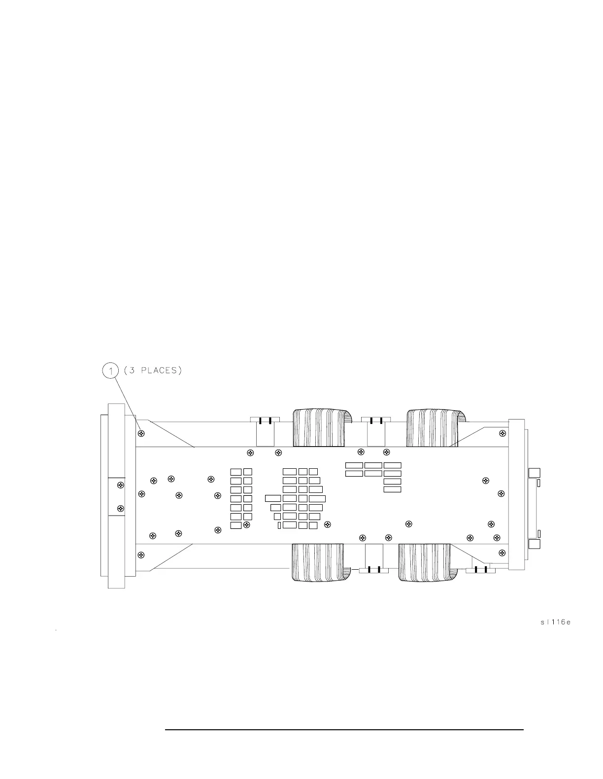
27.Remove the three screws (1) securing the front frame assembly to
the spectrum analyzer right side frame. See Figure 3-5 on page 164.
Figure 3-5 Front Frame Mounting Screws
28.Remove the three screws securing the front frame assembly to the
spectrum analyzer left side frame.
29.Remove the four screws (1) ( Figure 3-4 on page 163) securing the
CRT clamps to the deck.

 Loading...


