Chapter 10 515
Synthesizer Section
Troubleshooting Using the TAM
Troubleshooting Using the TAM
When using automatic fault isolation, the TAM indicates suspected
circuits that need to be manually checked. Use Table 10-4 on page 516
to locate the manual procedure.
Table 10-5 on page 517 lists assembly test connectors associated with
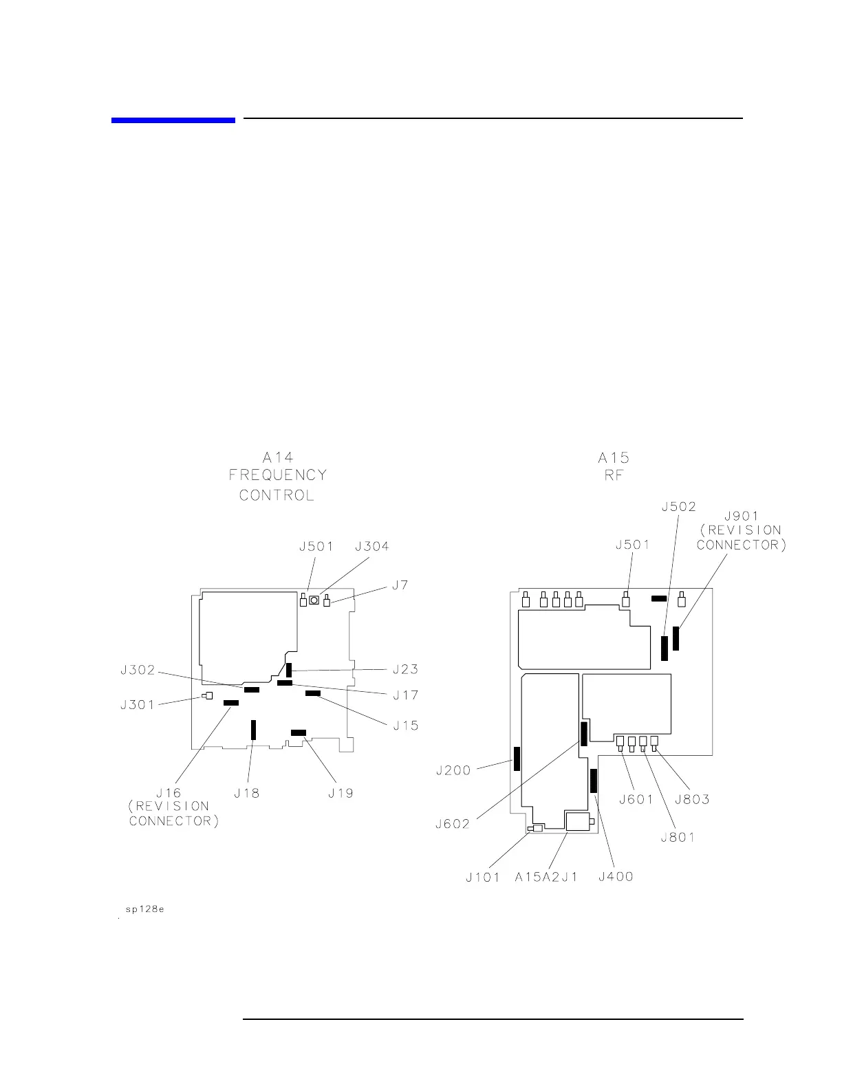
each manual probe troubleshooting test. Figure 10-3 on page 515
illustrates the location of A14 and A15 test connectors.
The pin locations of a 16-pin TAM connector are indicated in Figure
10-4 on page 516. Table 10-3 on page 516 indicates the correspondence
between a measured signal line and the TAM connector pin.
Figure 10-3 A14 and A15 Test Connectors

 Loading...


