Chapter 3 191
Assembly Replacement
Procedure 8. A7 through A13 Assemblies
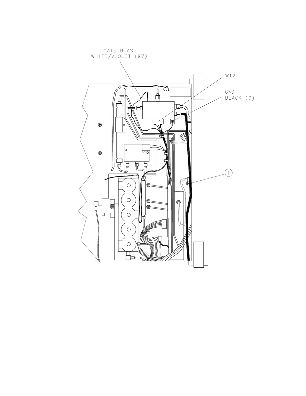
Figure 3-21 RF Section Bias Connections
A7 1st LO Distribution Amplifier
Removal
1. Remove the two screws securing the assembly to the spectrum
analyzer center deck.
2. Use a 5/16-inch wrench to disconnect W38 and W39 at A7J1 and J2.
3. Disconnect W42 (W43 on Option 002) at the front panel 1ST LO
OUTPUT connector. Loosen W42 (W43 on Option 002) at A7J3.

 Loading...


