Chapter 10 545
Synthesizer Section
Unlocked YTO PLL
indicated in the FREQ DIAGNOSE menu will be negative when
locking to lower sidebands. Refer to function blocks E, M, and N of
A14 frequency control schematic in the
Component Level Information.
Set the HP 8560E/EC to the following settings:
Center frequency .................................................. 300MHz
Span .............................................................................. 0Hz
37.Remove jumper A14J23 and connect a dc power supply to A14J23
pin 2. Connect ground to A14J23 pin 3. Set the dc power supply to
+7.5 Vdc.
38.Verify the nominal test-point voltages listed in Table 10-9 on
page 545.
39.Change the input voltage to −7.5 volts and re-verify that the voltages
listed in Table 10-9 on page 545 are the same except for a change in
polarity.
40.Change the
CENTER FREQ to 678.8 MHz with the span remaining 0
Hz. This will change the switch setting of U326A and invert the
voltages listed in Table 10-9 on page 545.
Check main coil coarse and fine DACs (steps 41-44)
41.The main coil coarse and fine DACs correct any initial pretune
errors in the YTO main coil. The DACs adjust the FM-coil current to
zero before any sweep begins. Refer to function block J of A14
frequency control schematic.
42.Set the HP 8560E/EC to the settings listed below. This sets both
DACs to 128 (the DAC setting range is 0 to 255).
Center frequency .................................................. 300MHz
Span .............................................................................. 0Hz
Trigger ......................................................... SINGLE,EXT
(with no external trigger connected)
43.Press
SAVE, PWR ON STATE and turn off the spectrum analyzer.
44.Place jumper A14J23 in the TEST position and turn on the spectrum
analyzer.
Check main coil tune DAC (steps 45-49)
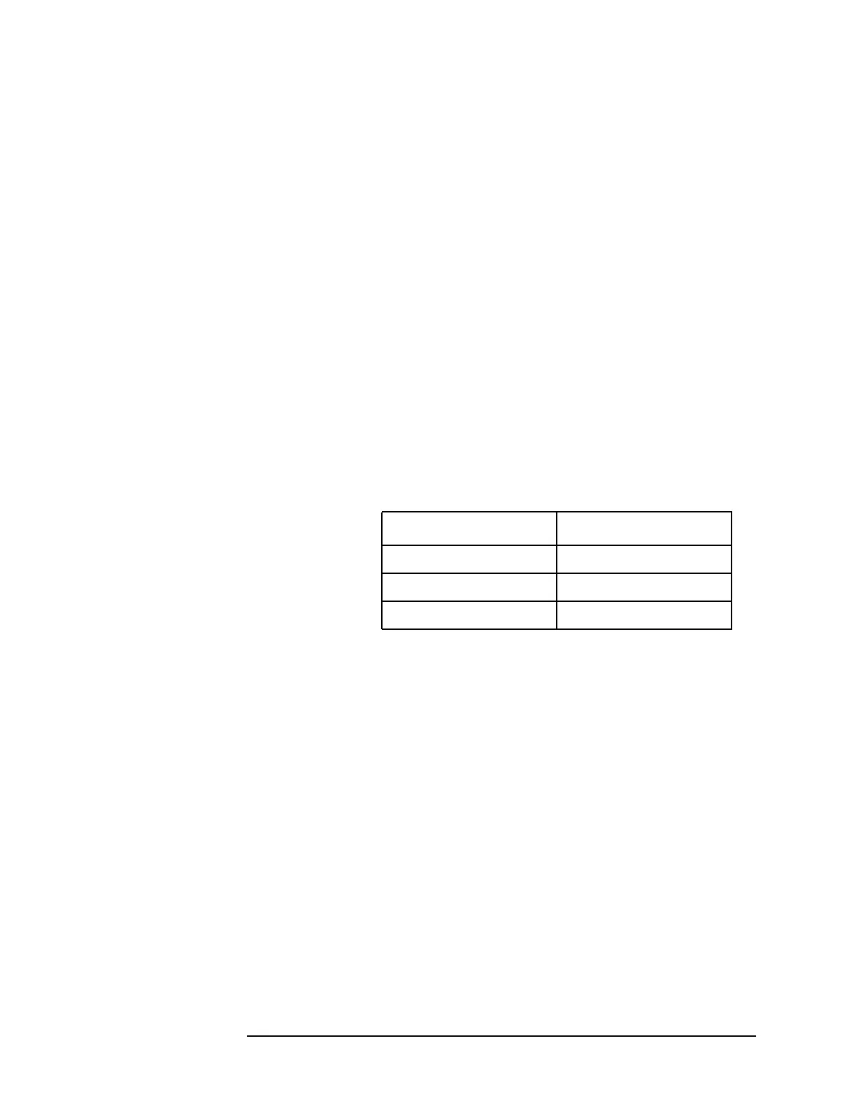
Table 10-9 Voltages in FM Coil and Main Loop Drivers
Measurement Points Voltages
A14U405 pin 6 +2.8 Vdc
A14U322 pin 2 0 Vdc
A14J17 pin 4 >+10 Vdc

 Loading...


